| Quantity | 3+ units | 10+ units | 30+ units | 50+ units | More |
|---|---|---|---|---|---|
| Price /Unit | $35.63 | $34.91 | $33.81 | $32.36 | Contact US |
 Finished HiFi Preamplifier Board DIY Audio Amplifier Board Replacement for Marantz HDAM Classic Preamplifier
$32.62
Finished HiFi Preamplifier Board DIY Audio Amplifier Board Replacement for Marantz HDAM Classic Preamplifier
$32.62
 Line Magnetic Audio LM-508IA 48W+48W Tube Amplifier Integrated Amplifier Tube Amp with Two VU Meters
$2,624.45
Line Magnetic Audio LM-508IA 48W+48W Tube Amplifier Integrated Amplifier Tube Amp with Two VU Meters
$2,624.45
 2x80W HiFi Digital Power Amplifier Board V1.6 Class D Amplifier Board for MERUS MA12070 with Toggle Switch
$33.44
2x80W HiFi Digital Power Amplifier Board V1.6 Class D Amplifier Board for MERUS MA12070 with Toggle Switch
$33.44
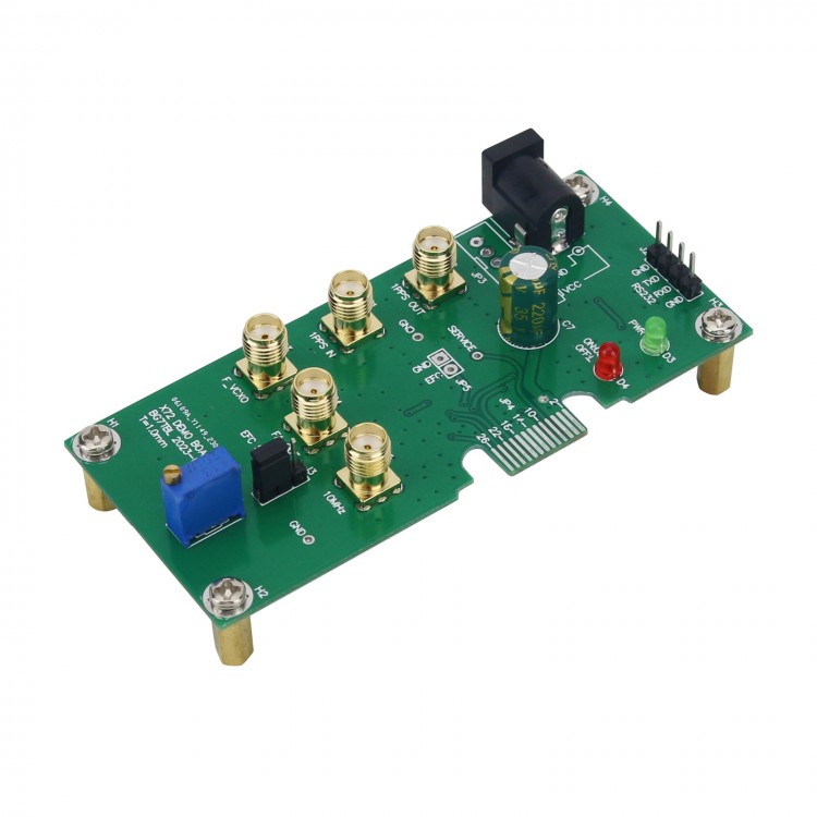
BG7TBL X72 Rubidium Clock Interface Board Atomic Clock Testing Board Support 1PPS Input and Output
Interface Description:
- J1: power interface, 5.5-2.1, onboard anti-reverse diode
- JP3: 4PIN, unwelded, directly connected with J1, suitable for wiring out
- D3: power indicator, green indicator light on when power on, otherwise light off
- D4: Locked LED, red; LED on for unlocked; LED off for lock
- RP1: frequency adjustment potentiometer, 0-5V output voltage range, chosen by J4 jumper whether to use it or not.
- J3: jumper, choose to use potentiometer or not
- JP4: to insert X72 rubidium clock, it needs to be fully inserted.
- JP5: EFC pin, input 0-5V, fine tune the frequency of the rubidium clock. If RP1 potentiometer is selected for connection, it is recommended to suspend the pin.
- P1-1PPS IN: 1PPS input
- P2-1PPS-OUT: 1PPS output
- P3-F_VCXO: rubidium clock 60M output
- P3-FA_OUT: FA_OUT, programmable output, support frequency adjustment with ox command
- P5-10MHz: 10M sine wave output
- J3: RS232 interface, directly connect the serial port of the computer, TX connect the RX pin of the serial port, RX connect to the TX pin of the serial port, 57600BPS
- Size: 90 x 43 x 25mm
- Fixing hole size: M3.0---82 x 33mm, distance to board border---3.5mm
- Weight: 70g
Precaution:
- If the height is not suitable, the height can be adjusted appropriately by adding or reducing shims;
- When using, it is necessary to fix the circuit board to prevent poor contact;
- When adjusting the potentiometer, be sure to fix the circuit board properly, otherwise it may cause poor contact and significant frequency fluctuations.
FAQ:
Q: What should I do if the green light on the circuit board does not light up after power on?
A: Check if the power supply is plugged in properly and if the power supply is sufficient. It is recommended to use a 15V 3A power supply (not included). If the power supply is normal, it may be a malfunction of the rubidium clock. It is recommended to check the rubidium clock.
Q: After powering on, the green light is on, while the red light remains on and cannot be extinguished. What should I do?
A: The rubidium clock is malfunctioning. It is recommended to check the rubidium clock.
Q: Just powered on, the green light and the red light is on. After a while, the red light goes out, and after a while, the red light on again. What should I do?
A: The rubidium clock is malfunctioning. It is recommended to check the rubidium clock.
Q: Just powered on, the green light and the red light is on, and after a while, the red light becomes dim, but it doesn't go out. What should I do?
A: The rubidium clock is malfunctioning. It is recommended to check the rubidium clock.
Q: Just powered on, the green light is on, but the red light remains off. What should I do?
A: The rubidium clock is malfunctioning. It is recommended to check the rubidium clock.
Q: After connecting the potentiometer, no matter how the potentiometer is adjusted, the frequency cannot be adjusted to 10M
A: The rubidium clock needs to be adjusted or has a malfunction. It is recommended to check the rubidium clock.
Q: After connecting to SMA, why cannot check the 10M output?
A: Check if the SMA interface has good contact. If contact well, there is a possibility of rubidium clock malfunction. It is recommended to check the rubidium clock.
Package Included:
- 1 x Board


")
")
")

