| Quantity | 3+ units | 10+ units | 30+ units | 50+ units | More |
|---|---|---|---|---|---|
| Price /Unit | $288.02 | $282.14 | $273.33 | $261.57 | Contact US |
 H2MD DC24-120V 6A Engraving Machine CNC Stepper Motor Driver Module Support Phase Dislocation Protection
$45.54
H2MD DC24-120V 6A Engraving Machine CNC Stepper Motor Driver Module Support Phase Dislocation Protection
$45.54
 ZM-3H2080 24V High Performance 3-Phase Stepper Motor Driver Controller AC80-220V for 86-130MM Stepper Motors
$166.32
ZM-3H2080 24V High Performance 3-Phase Stepper Motor Driver Controller AC80-220V for 86-130MM Stepper Motors
$166.32
 ZM-3H2080 12V High Performance 3-Phase Stepper Motor Driver Controller AC80-220V for 86-130MM Stepper Motors
$166.32
ZM-3H2080 12V High Performance 3-Phase Stepper Motor Driver Controller AC80-220V for 86-130MM Stepper Motors
$166.32
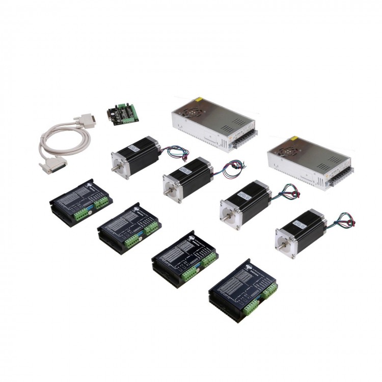
1.Nema 23 stepper motorCNC 4Axis Nema 23 Motor 425oz-in 3A Driver DM542A 128Microstep w/ Power Supply & Breakout Board What's in Box?4 pcs Nema 23 stepper motor with 425 oz.in4 pcs stepper motor driver DM542A, peak 4.2A, 128 micsteps, replacing M5422 pcs Power supply 350Watts (36VDC/9.7A)1 pc Breakout board & 1 pc Parallel cable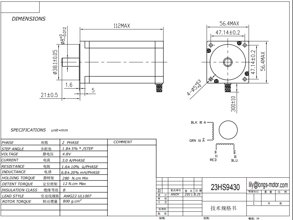 2. Stepper motor driver- DM542A:
 Detailed information DM542A
is a type of two-phase hybrid stepping motor driver, The drive voltage
of which is from 18VDC to 50VDC. It is designed for use with 2-phase
hybrid stepper motor of all kinds with 42mm to 86mm outside diameter and
less than 4.0A phase current. This circuit that it adopts is smiliar to
the circuit of servo control which enables the motor run smoothly
almost without noise and vibration. Hording torque when DM542A run under
high speed is also significantly higher than the other two-phase
driver, whats more, the positioning accuracy is also higher. It is
widely used in middle and big size numerical control devices such as
curving machine, CNC machine, computer embroider machine, packing
machines and so on.Features:l High performance, low pricel Average current control, 2-phase sinusoidal output current drivel Supply voltage from 18VDC to 50VDCl Opto-isolated signal I/Ol Overvoltage, under voltage, overcorrect, phase short circuit protectionl 15 channels subdivision and automatic idle-current reductionl 8 channels output phase current settingl Offline command input terminall Motor torque is related with speed, but not related with step/revolutionl High start speedl High hording torque under high speedElectrical specification:Input voltage18-50VDCInput current< 4AOutput current1.0A~4.2AConsumptionConsumption:80W; Internal Insurance:6ATemperatureWorking Temperature -10~45?;Stocking temperature -40?~70?HumidityNot condensation, no water dropletsgasProhibition of combustible gases and conductive dustweight200GPins assignments and description: 1) Connector Pins Configurations
Detailed information DM542A
is a type of two-phase hybrid stepping motor driver, The drive voltage
of which is from 18VDC to 50VDC. It is designed for use with 2-phase
hybrid stepper motor of all kinds with 42mm to 86mm outside diameter and
less than 4.0A phase current. This circuit that it adopts is smiliar to
the circuit of servo control which enables the motor run smoothly
almost without noise and vibration. Hording torque when DM542A run under
high speed is also significantly higher than the other two-phase
driver, whats more, the positioning accuracy is also higher. It is
widely used in middle and big size numerical control devices such as
curving machine, CNC machine, computer embroider machine, packing
machines and so on.Features:l High performance, low pricel Average current control, 2-phase sinusoidal output current drivel Supply voltage from 18VDC to 50VDCl Opto-isolated signal I/Ol Overvoltage, under voltage, overcorrect, phase short circuit protectionl 15 channels subdivision and automatic idle-current reductionl 8 channels output phase current settingl Offline command input terminall Motor torque is related with speed, but not related with step/revolutionl High start speedl High hording torque under high speedElectrical specification:Input voltage18-50VDCInput current< 4AOutput current1.0A~4.2AConsumptionConsumption:80W; Internal Insurance:6ATemperatureWorking Temperature -10~45?;Stocking temperature -40?~70?HumidityNot condensation, no water dropletsgasProhibition of combustible gases and conductive dustweight200GPins assignments and description: 1) Connector Pins ConfigurationsPin Function Details PUL +,PUL- Pulse signal, PUL+ is the positive end of pulses input pin PUL- is the negative end of pulse input pin DIR+,DIR- DIR signal: DIR+ is the positive end of direction input pin DIR- is the negative end of direction input pinENBL+ Enable
signal: ENBL+ is the positive end of direction input pin. This signal
is used for enabling/disabling the driver. High level for enabling the
driver and low level for disabling the driver. ENBL- ENBL- is the negative end of direction input pin. Usually left unconnected (enabled) 2) Pins wiring diagram:PC’s control signals can be active in high and low electrical level. When the high electrical levelis active, all control negative signals will be connected together to GND. When low electricallevel is active, all control positive signals will be connected together to public port. Now givetwo examples( Open collector &PNP), please check them: Fig 1. Input port circuit (Yang connection) PC open connector output Fig. 2 Input port circuit ( Yin connection) PC PNP outputNote: When VCC=5V, R=0 When VCC=12V, R=1K, >1/8W When VCC=24V, R=2K,>1/8WR must connect in the control signal part . 3.Function choice ( Using DIP pins to achieve this function)1) Micro step resolution is set by SW 5,6,7,8 of the DIP switch as shown in the following table: SW5OFFONOFFONOFFONOFFONOFFONOFFONOFFONOFFSW6ONOFFOFFONONOFFOFFONONOFFOFFONONOFFOFFSW7ONONONOFFOFFOFFOFFONONONONOFFOFFOFFOFFSW8ONONONONONONONOFFOFFOFFOFFOFFOFFOFFOFFPULSE/REV400800160032006400128002560010002000400050008000100002000025000 2) Standstill current settingSW4 is used for this purpose. OFF meaning that the standstill current is set to be half of theselected dynamic current and ON meaning that standstill is set to be the same as the selecteddynamic current. 3) Output current setting:The first three bits (SW 1, 2, 3)of the DIP switch are used to set the dynamic current.Select a setting Closest to your motor’s required current Output current (A)SW1SW2SW3PEAKRMSONONON1.000.71OFFONON1.461.04ONOFFON1.911.36OFFOFFON2.371.69ONONOFF2.842.03OFFONOFF3.312.36ONOFFOFF3.762.69OFFOFF


")
")
")
")


")
