| Quantity | 3+ units | 10+ units | 30+ units | 50+ units | More |
|---|---|---|---|---|---|
| Price /Unit | $66.33 | $64.97 | $62.94 | $60.24 | Contact US |
 SUP-C703S Signal Generator & Process Calibrator – mA, V, Ω, RTD, Thermocouple Output & Measurement
$156.44
SUP-C703S Signal Generator & Process Calibrator – mA, V, Ω, RTD, Thermocouple Output & Measurement
$156.44
 6000A 20µH Air Core Inductor for Dual Pulse Testing and High-Performance Electrical Experiments
$86.76
6000A 20µH Air Core Inductor for Dual Pulse Testing and High-Performance Electrical Experiments
$86.76
 DP8000 Max IGBT Pulse Generator with Internally Integrated IGBT Driver (Air Core Inductor Included)
$384.16
DP8000 Max IGBT Pulse Generator with Internally Integrated IGBT Driver (Air Core Inductor Included)
$384.16
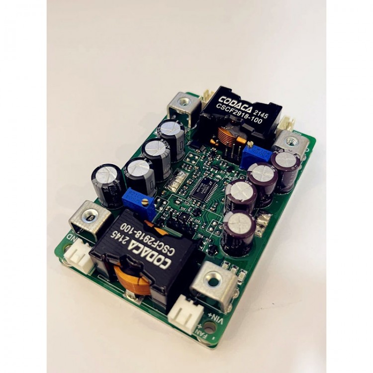
DC Buck Converter Board Step down Module Enables Current Regulation Input 12-56V Output 2-54V 0-50A
Read before purchasing:
- Do not use a 3A/5A regulated DC power supply as an input to test the power supply.
- Basic technical knowledge and hands-on ability are highly recommended.
- Certain power supply test and measurement capabilities and equipment are recommended. Do not test this power supply with a 3A adjustable regulated power supply used in labs.
- Do not test the current-limiting power supply in CC mode of an electronic load.
- The non-isolated buck power supply is back-fed into the input. There will be a small quiescent current if the output is connected to a battery all the time. If the input can accept back-filling, special treatment is not required.
- The continuous mode CCM of the power supply is powered down at the input and connected to a high-voltage battery at the output, which will reversely boost and burn out the power supply.
If charging is required, it is recommended to purchase an ideal diode to connect to the output for isolation and switch to intermittent mode operation (The no-load current of discontinuous mode is small, EMI is poor at low output current, and the noise is large, which is not suitable for connecting sensitive equipment such as speakers, but the output can be connected to battery; Continuous mode has no-load current, good EMI, no noise, fast response, and ideal diode isolation is required for battery charging).
Package Included:
- 1 x Power supply board with current regulation
Note:
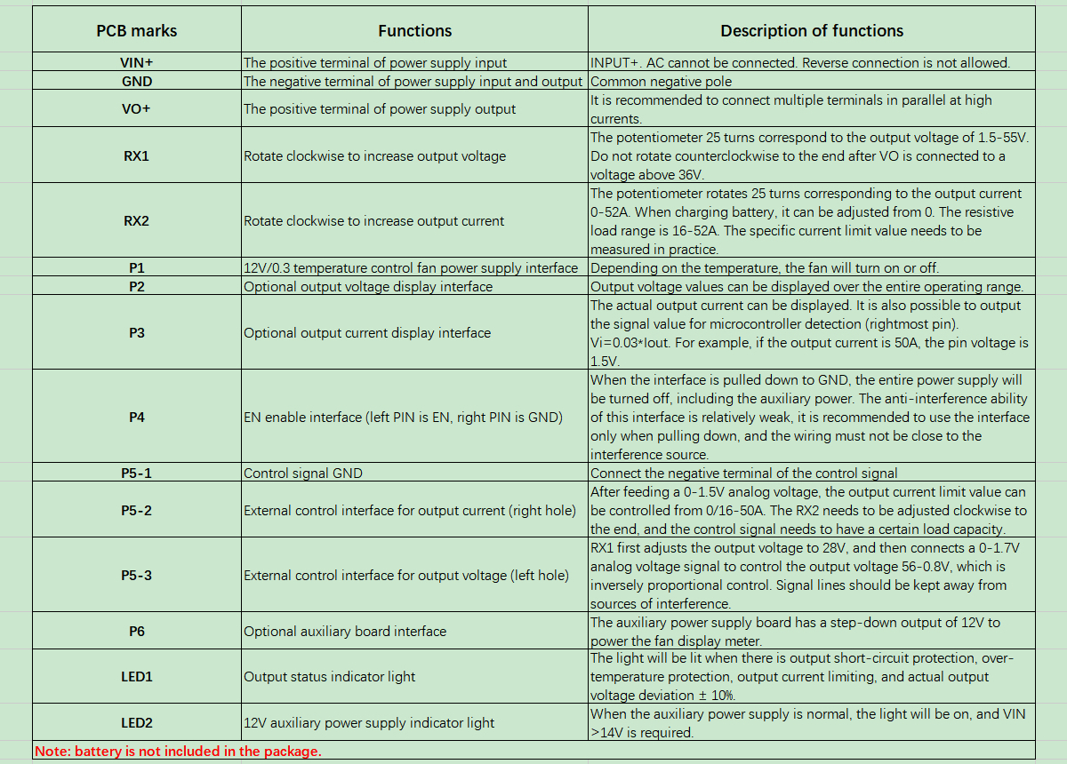
- Battery is not included in the package.
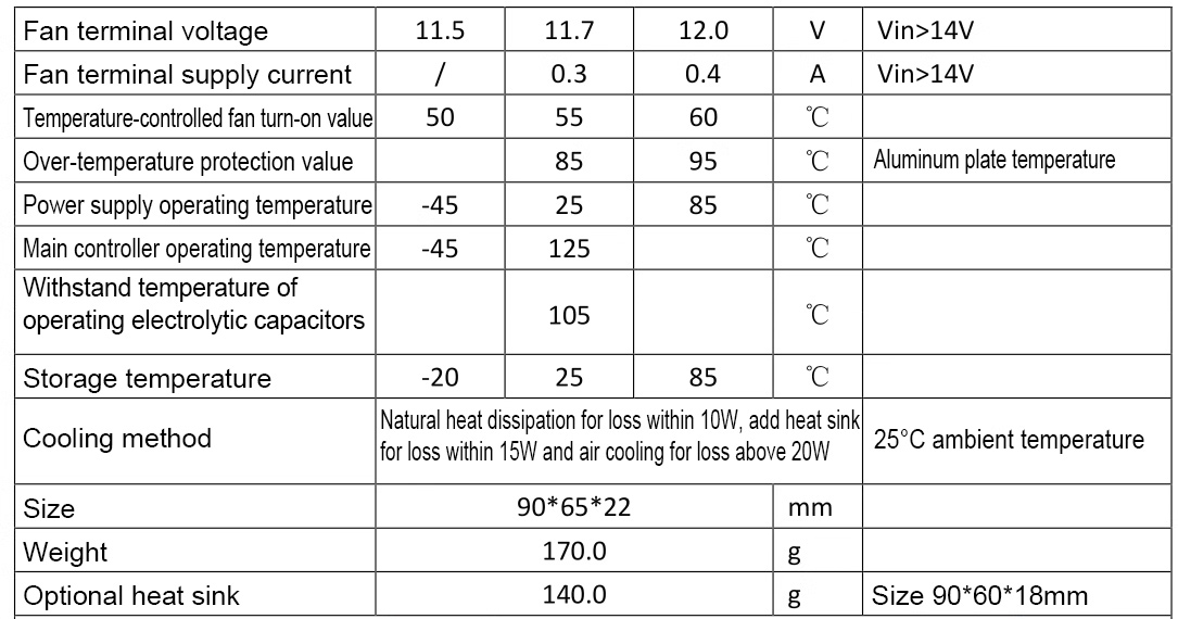
Typical Performance (YF-BK60V40A):
- Non-isolated synchronous buck power supply
- Wide input DC 12-58V, output DC 2.0-54V
- Peak efficiency> 98%
- Over-current protection, short-circuit protection self-recovery
- Remote ON/OFF, over-temperature protection, and optional temperature-controlled fan
- Constant current indicator light
- Work indicator light
- Output voltage and current are adjustable and externally controllable
- Optional voltage and current display
- High voltage regulation accuracy
- Ultra-fast transient response
- Aluminum substrate with high thermal conductivity design, constant frequency operation MEI is convenient to predict
- Power can be more than 1000W (output>24V)
- All tests are made at 48V input voltage, continuous mode, resistive load, and room temperature at 25°C. Parameters are subject to change without notice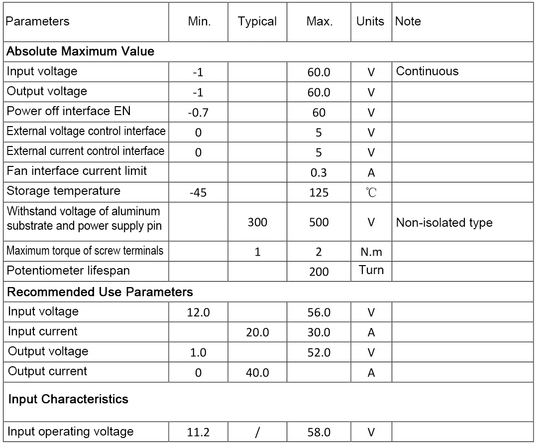
Attention:
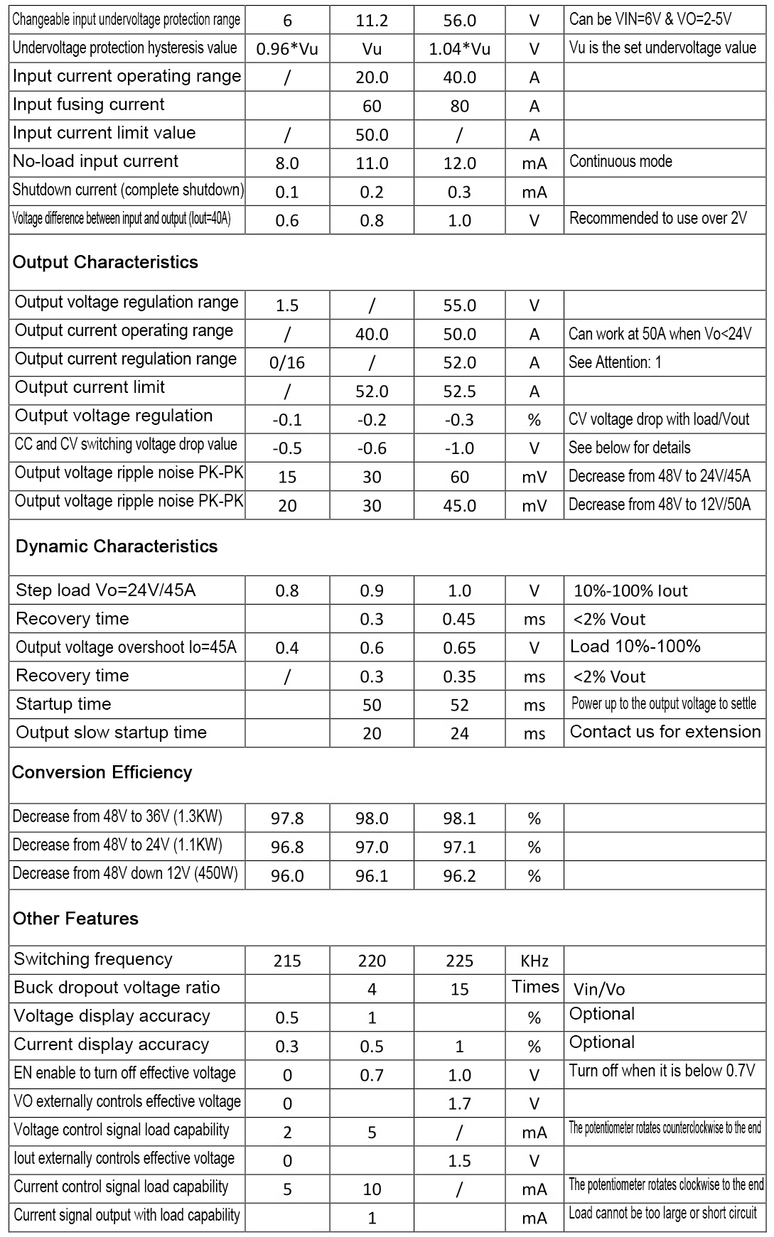
1. When the output is a resistive load (resistor, LED), the output current cannot be adjusted to within 16A, and there is a minimum value requirement. When the output is used to charge a battery, the current can be adjusted from 0. Or contact us to modify to a low current limit.
2. The default discontinuous mode can be connected to battery for charging. It is also recommended to add an ideal diode and set a good input undervoltage protection value to avoid the output voltage being back-fed into the input. It can be modified to continuous working mode (with good dynamic response, small ripple and interference. Suitable for sensitive equipment such as speakers).
3. Output current 50A for long-term operation is only when the output is less than 24V. Other high output voltages require a 20-30% derating.
4. When the start-up time of the input power supply is long, users need to adjust the start-up time. For example, the AC adapter output full-load voltage settling time is 50ms, while the start-up time of this power supply is 20ms, which may cause AC to fail to start properly with load. It is recommended to power up before testing with load. Or contact us to modify the startup time.
5. When the output constant voltage and constant current switching is critical, there will be a deviation of 0.5-1V in the constant voltage stage. For example, if the no-load is 29.4V and the current limit is set to 20A, the current will be constant at 20A (-5%) when the output voltage is less than 28.7V. At 28.8-29.0V, the current may be 18-15A, which is also affected by the internal resistance of the wire and the internal resistance of the battery. Constant voltage mode is subject to load regulation.
6. For different applications, some parameters may need to be adjusted to achieve the best state.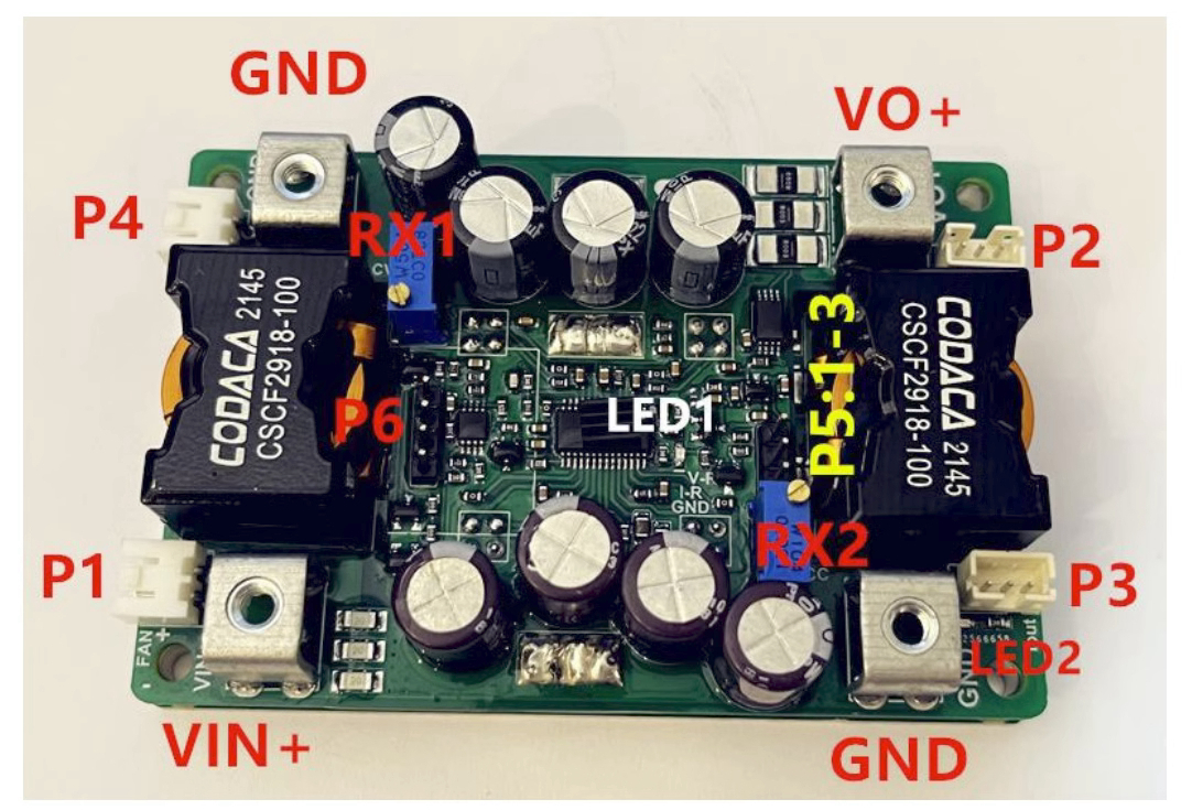
Attention:
1: When testing this power supply, it must be ensured that the input source can provide a large enough current (>50A) to ensure that the power supply does not collapse or even be damaged.
2: The startup time of the input source must be less than the startup time of this power supply (such as the adapter as input), otherwise it may not be possible to start with load. It is recommended to power on before performing tests with load.
3: The input wire connected to this power supply shall not be too long (the internal resistance of the wire shall not be too large), otherwise the power supply may cause oscillation and abnormality.
4: If there is a diode in series with the input source to this power supply, the power supply may be damaged by over-voltage due to the boost effect of the wire at the moment of turning on and disconnecting. In this case, input should not exceed 48V.
5: Do not use the CC mode of electronic load to test the current limiting of this power supply. CR mode is required. CC mode absorbs current, this power supply is current limited, and in constant current mode, this will cause this power supply to collapse or even damage.
6: The current limit value setting should use resistor CR mode or battery with electric quantity < 60%. For example, first set the no-load voltage to 29.4V, and then set the current limit value to 20A, the load resistance is 0.88Ω~1.17Ω (29.4*0.6/20A<R<29.4*0.8/20A). A 1Ω resistor can be used, and the potentiometer is adjusted until the output current is 20A.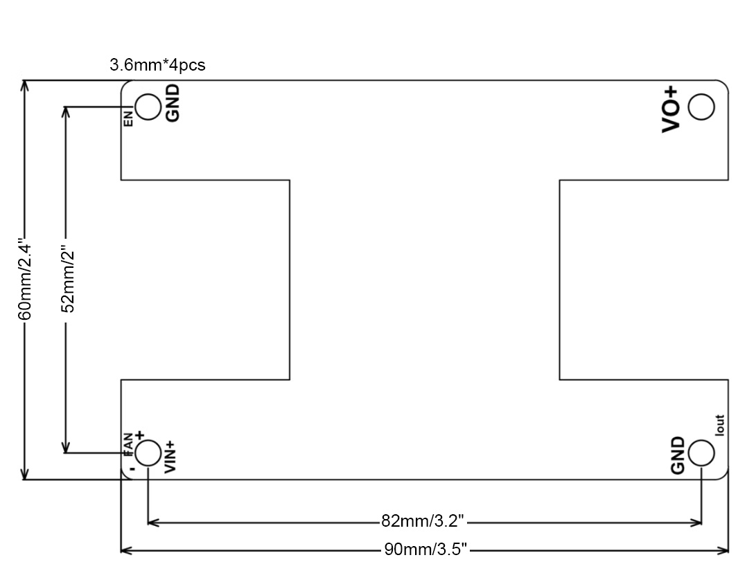
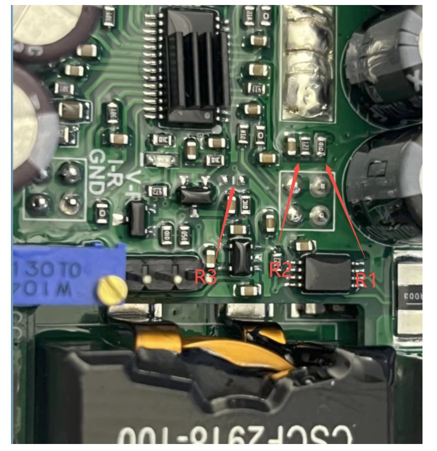
Modify input undervoltage protection value:
- R1 and R2 are resistors. Input undervoltage protection value V=(R1/R2+1)*1.2V. For example, the default is V=(100K/12K+1)*1.2V=11.2V. If it needs to be modified to other protection values, it can be obtained by changing R1 and R2. It is recommended that buyers leave a message when placing an order to modify the input undervoltage protection value. In this way, we can modify the protection value before shipment.
- Modification method of continuous mode: R3 welded with OR-10K resistor. Suitable for sensitive equipment applications, but the no-load current will be large.