| Quantity | 3+ units | 10+ units | 30+ units | 50+ units | More |
|---|---|---|---|---|---|
| Price /Unit | $34.67 | $33.96 | $32.90 | $31.49 | Contact US |
 DMS-72G Aluminum Plate Letter Manual Embosser Machine Convex Character Stamping Embossing for Aluminum Dog Tag/PVC Card
$383.77
DMS-72G Aluminum Plate Letter Manual Embosser Machine Convex Character Stamping Embossing for Aluminum Dog Tag/PVC Card
$383.77
 2025 LibreVNA 100K-6GHz Dual Port Vector Network Analyzer 110dB Dynamic with Spectrum and Signal Source Function
$670.61
2025 LibreVNA 100K-6GHz Dual Port Vector Network Analyzer 110dB Dynamic with Spectrum and Signal Source Function
$670.61
 PicoScope 4824A 8-Channel 20MHz 12Bit High Resolution Deep-memory Oscilloscope Arbitrary Waveform Function Generator
$3,116.44
PicoScope 4824A 8-Channel 20MHz 12Bit High Resolution Deep-memory Oscilloscope Arbitrary Waveform Function Generator
$3,116.44
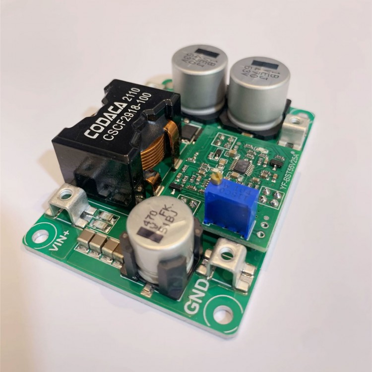
DC-DC Boost Converter Step up Converter 12V 24V 48V High Power Adjustable 5-32V/18A Output 12-52V
Read before purchasing:
- Basic technical knowledge and hands-on ability are highly recommended.
- Certain power supply test and measurement capabilities and equipment are recommended. Do not test this power supply with a 3A adjustable regulated power supply used in labs.
- Do not test the current-limiting power supply in CC mode of an electronic load.
- Output current adjustment range: If the input power is sufficient, and the output power supply is 20V and a 0.4Ω resistor is connected to adjust CC potentiometer, the output current can be adjusted to a maximum of 50A, but cannot be adjusted to the minimum limit value (except 0A).
Recommended Use:
1: It is recommended to use the input current within 15A, and the efficiency will be the best.
2: The input and output voltage difference should not be too large, up to 4 times (e.g. 12V boost to 48V)
3: It needs to be derated for high temperature environment.
4: The output uses constant voltage application and it is not recommended to use it for charging.
Typical Performance:
- Non-isolated boost power supply
- Wide input DC5-32V, output DC9-52V
- Peak efficiency> 97.5%
- Input fuse short-circuit protection
- Over-temperature protection self-recovery
- Adjustable output voltage
- Potentiometer open circuit protection
- Fast dynamic response in continuous mode
- High frequency operation with low EMI performance
- Load indicator light and fault indicator light
- Power can be over 500W (input >24V), aluminum substrate design, high thermal conductivity, 90°C normal work
- All tests are made at 14V input voltage, resistive load and 25°C room temperature. Parameters are subject to change without notice
Attention:
1: The boost output capacitor ripple current is large, which reduces the capacitor heating and prolongs the life. Electrolytic capacitors can be connected in parallel.
2: Battery cannot be charged because the current limit cannot be limited, and the input will work at a maximum of 33A.
3: When the input source start-up time is long, you need to adjust the output slow start time. For example, the settling time of the AC adaptation output full load voltage is 50ms, and the start-up time of this power supply is 2ms, which may cause AC to fail to start normally with load, and it is necessary to start the AC power supply first and then start the DC power supply.
4: The boost power supply output cannot be turned off. After undervoltage protection, the output voltage is the input voltage value, which is in the pass-through state.
Package Included:
- 1 x Power supply board
Note:
- Battery is not included in the package.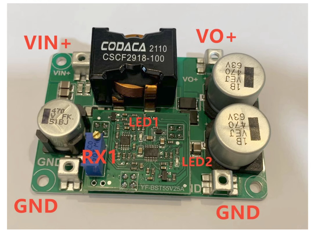
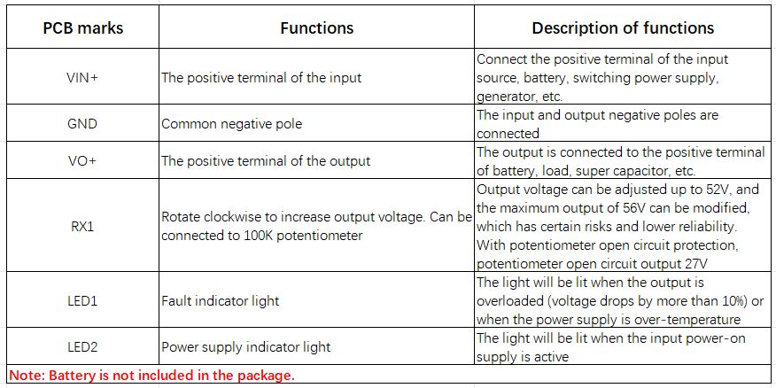
Attention:
- When there is fault, the light will be be lit. 2 lit indicator lights indicate it is working normally.
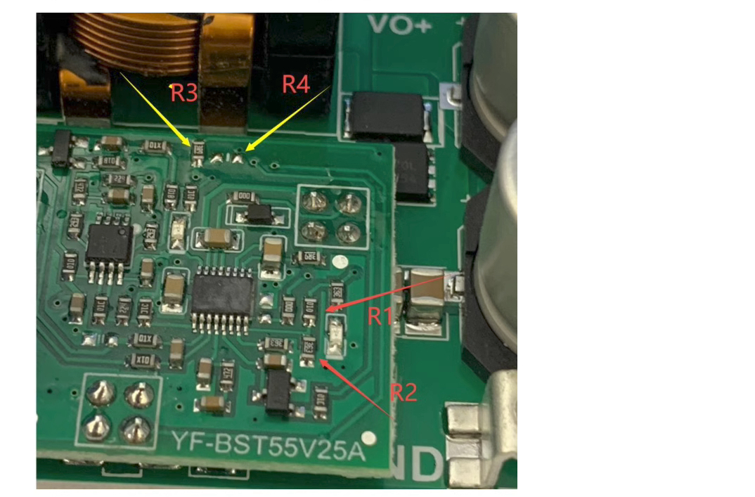
1. Modify undervoltage protection value
As shown in the figure, the resistors of the red arrows is R1 and R2, respectively. Undervoltage shutdown value V={(R1/R2)+1}*1.2V. For example, the default is V=(100K/36K+1)*1.2=4.53V. Note: When there is undervoltage protection, the output cannot be completely disconnected without boosting. After undervoltage, the output is the input voltage value.
2. A modification method that can continue to work when it inputs 2.5V
- As shown in the figure, the resistor R3 of the yellow arrow is removed and soldered to the right R4 position, and it can continue to operate when the input voltage drops to 2.5V after starting up operation at 5V. (Note that the undervoltage protection needs to be modified to within 2.5V, and the output voltage setting value should not be greater than 36V.) It is recommended that the maximum output voltage is within 15V).
- You can also remove the arrow resistor, and the lower bonding pad is soldered with a wire to connect the external 5V-24V, so that the input is 2.5-32V and it can also start to work.