| Quantity | 3+ units | 10+ units | 30+ units | 50+ units | More |
|---|---|---|---|---|---|
| Price /Unit | $5.91 | $5.79 | $5.61 | $5.37 | Contact US |
 ANNOY TOOLS 3-Axis CNC Controller Board GRBL 1.1f with USB Cable for Offline Controller 500W Spindle
$34.79
ANNOY TOOLS 3-Axis CNC Controller Board GRBL 1.1f with USB Cable for Offline Controller 500W Spindle
$34.79
 5pcs Top Suction Plates Rubber Suction Pad (125mmx75mmx17mm with Large Hole) for Vacuum Blocks
$39.60
5pcs Top Suction Plates Rubber Suction Pad (125mmx75mmx17mm with Large Hole) for Vacuum Blocks
$39.60
 5pcs Top Suction Plates Rubber Suction Pad (125mmx75mmx17mm with Small Hole) for Vacuum Blocks
$39.60
5pcs Top Suction Plates Rubber Suction Pad (125mmx75mmx17mm with Small Hole) for Vacuum Blocks
$39.60
Dual Mode PWM Generator & Pulse Generator Frequency Duty Cycle Adjustable Module without Shell ZK-PP1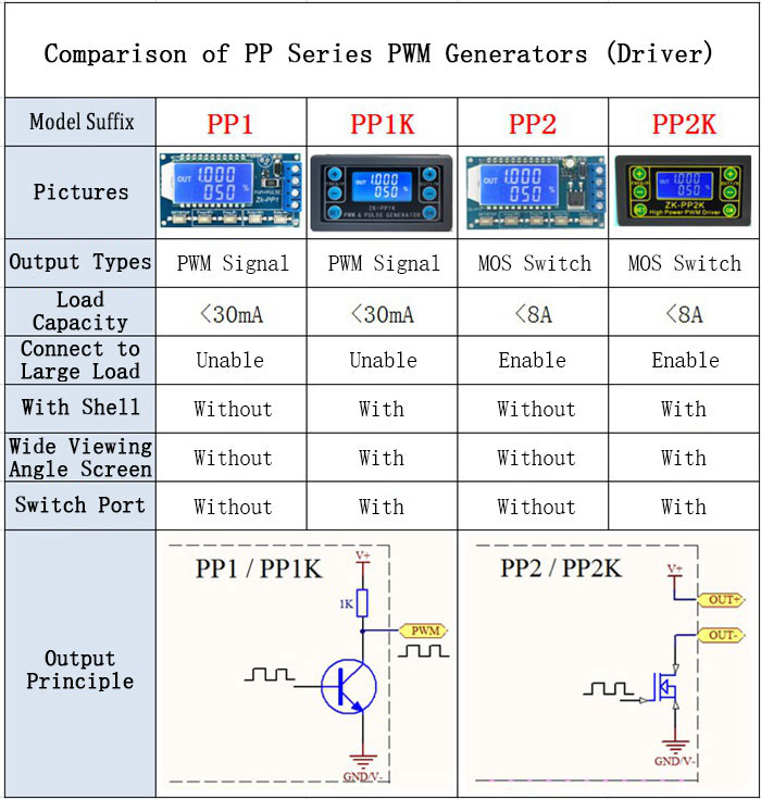
Applications:
- PWM signal generator, square wave rectangular wave signal generator.
- Used to generate square wave rectangular wave signal for controlling DC motor or stepper motor driver; used for servo motor, stepper motor, electric gripper, replacing PLC pulse, etc. The PULSE mode can be used to control the number of pulses, which can control the rotation turns of your stepper motor.
- Matching driver can realize dimming, speed regulation, control solenoid valve, etc., but can not directly drive loads such as electric lamp motor solenoid valve.
Features:
- Two Switchable Modes: PWM Mode: Frequency (continuous), duty cycle. Please note that the number of pulses cannot be set in this mode. Pulses are sent continuously in this mode. PULSE Mode: Positive pulse width time, negative pulse width time, delayed start time, and number of pulses are adjustable.
- With start and stop button, you can control the output and stop of signals.
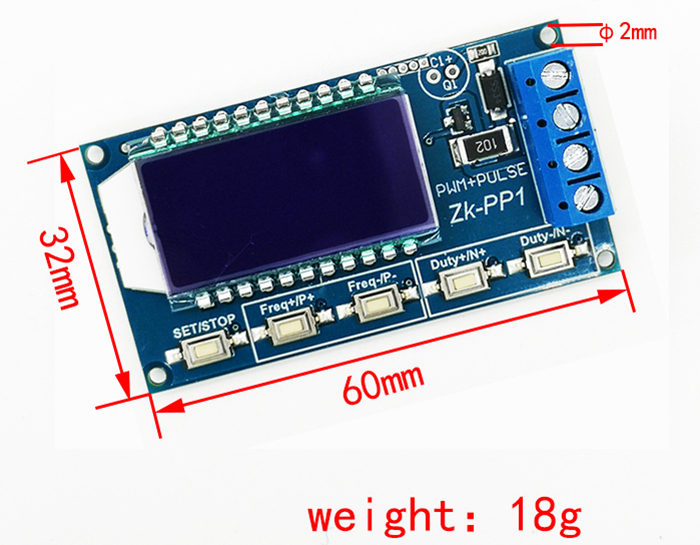
- Wide voltage input 3.3-30V, with reverse connection protection and 5.08mm wiring terminal.
Technical Parameters:
- Working voltage: 3.3~30V, with anti-reverse protection
- Frequency range: 1Hz~150KHz, accuracy about 2%
- Duty cycle range: 0-100%, 1% stepping
- Number of pulses: 1-9999, or infinite (---- displayed stands for infinity)
- Delay output time: 0.000s-9999s.The minimum can be set 1ms
- Positive and negative pulse width length: 0.000s-9999s. The minimum can be set 1ms
- Signal loading capacity: less than 30mA
- Output signal amplitude: amplitude is equal to supply voltage
- Product size: 60mm*32mm*10mm
- Product Weight: 18g
Module Introduction:
1.Operation Via Buttons: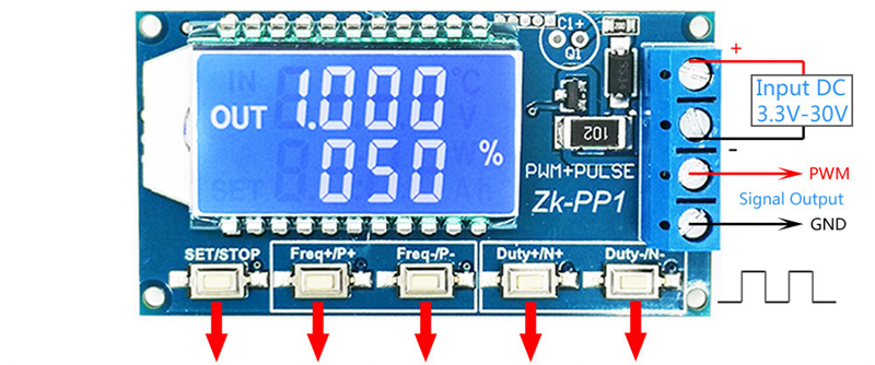
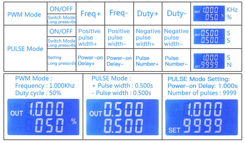
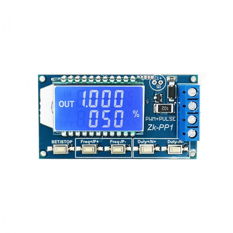
2. PWM Mode (display with % for PWM mode)
The factory default mode is PWM mode. Set frequency through buttons FREQ+ and FREQ-. Set duty cycle via buttons DUTY+ and DUTY-. Short press button STOP to control signals' output or stop. Output is 0 when stopped. When OUT mark is displayed on the screen, the module has output. Otherwise, the output is stopped. Default factory frequency is 1KHZ and duty cycle is 50%.
If you need to switch to PULSE pulse mode, press and hold button SET (more than 6 seconds). Do not release it, you will see the screen change and % disappear. Now the module is in PULSE mode.
3. PULSE Mode (No % on the right side of the display is PULSE mode)
By buttons P + and P-, you can set positive pulse width time which is displayed on LCD screen. Press N + and N- buttons to set negative pulse width time, which will be displayed on LCD screen, with unit in seconds. Short press button STOP to control signal to output or stop. Output is 0 when stopped. The module has output when the screen displays OUT. Otherwise, output is stopped. Default positive pulse width is 0.5 seconds, and negative pulse width is 0.5 seconds.
Setting of pulse number and delay time: In PULSE mode, long press button SET for 2 seconds, then release it to enter pulse number and delay time setting interface. The screen displays SET. After entering the interface, output pulse will be turned off and cleared.
Set delay time by pressing buttons P + and P-. Set the number of pulses by pressing buttons N + and N-. Default delay time is 0 seconds and default number of pulses is infinite (display ----). Press and hold SET button for 2 seconds, the module will automatically return to pulse interface. Press button STOP. After delay setting time is completed, the set number of pulses will be sent. After sending the pulse number, the module will output 0 automatically. If the period is not completed, press STOP button to turn off and clear output pulse. The number of pulses set will be sent every time it is started.
Application Operation Examples:
1. PWM output 20KHZ, 60% duty cycle: Select PWM mode, set frequency to 20.00 and duty cycle to 060%.
2.Turn on output end for 0.6 seconds and turn off for 0.2 seconds, infinite loop: select PULSE mode, set positive pulse width to 0.600, set negative pulse width to 0.200, set delay time to 0.000, and set the number of pulses to ----.
3.Power on or press SET/STOP button, delay for 5 seconds, then turn on output end for 0.6 seconds, turn off output end for 0.2 seconds, infinite loop: select PULSE mode, set positive pulse width to 0.600, set negative pulse width to 0.200, set delay time to 5.000, and the number of pulses is set to ----.
4. Power on or press SET/STOP button, delay 5 seconds, and then output 100 pulses with high level 10ms and low level 10ms: Select PULSE mode, set positive pulse width to 0.010, set negative pulse width to 0.010, and set delay time to 5.000 and the number of pulses is set to 0100.
5. After power on delay for 10 seconds, and then output signals permanently: select PULSE mode and set positive pulse width to a number greater than 0. Set negative pulse width to 0, set delay time to 10.00 seconds, and the number of pulses to infinite (----).
6.Other applications can explore by yourselves or consult customer service.
7.All setting parameters will not be lost after shutdown.
Package Included:
- 1 x PWM Pulse Generator