| Quantity | 3+ units | 10+ units | 30+ units | 50+ units | More |
|---|---|---|---|---|---|
| Price /Unit | $8.48 | $8.30 | $8.04 | $7.70 | Contact US |
 SUP-C703S Signal Generator & Process Calibrator – mA, V, Ω, RTD, Thermocouple Output & Measurement
$156.44
SUP-C703S Signal Generator & Process Calibrator – mA, V, Ω, RTD, Thermocouple Output & Measurement
$156.44
 6000A 20µH Air Core Inductor for Dual Pulse Testing and High-Performance Electrical Experiments
$86.76
6000A 20µH Air Core Inductor for Dual Pulse Testing and High-Performance Electrical Experiments
$86.76
 DP8000 Max IGBT Pulse Generator with Internally Integrated IGBT Driver (Air Core Inductor Included)
$384.16
DP8000 Max IGBT Pulse Generator with Internally Integrated IGBT Driver (Air Core Inductor Included)
$384.16
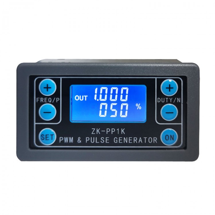
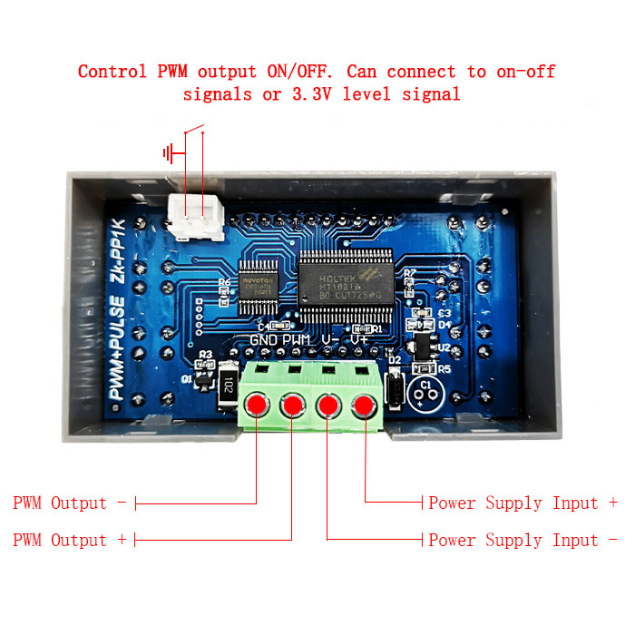
Dual Mode PWM Generator & Pulse Generator Frequency Duty Cycle Adjustable Module with Shell ZK-PP1K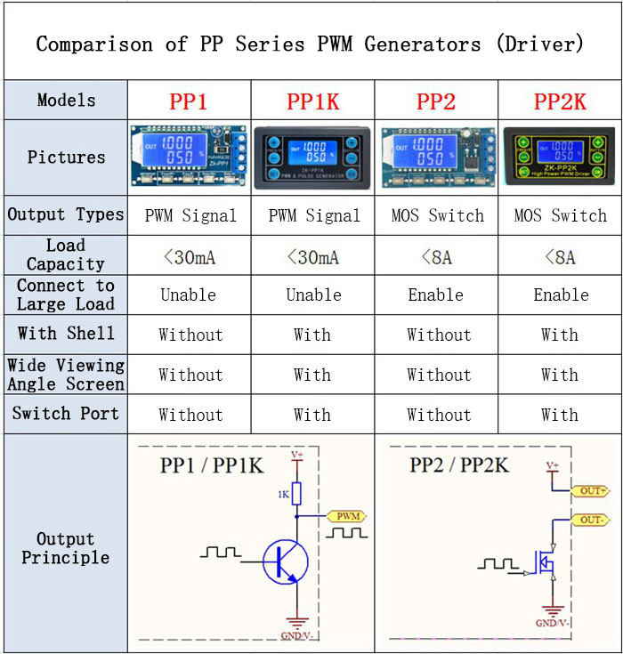
 Applications:
- PWM signal generator, square wave rectangular wave signal generator.
- Used to generate square wave rectangular wave signal for controlling DC motor or stepper motor driver; used for servo motor, stepper motor, electric gripper, replacing PLC pulse, etc. The PULSE mode can be used to control the number of pulses, which can control the rotation turns of your stepper motor.
- Matching driver can realize dimming, speed regulation, control solenoid valve, etc., but can not directly drive loads such as electric lamp motor solenoid valve.
Features:
- Two Switchable Modes: PWM Mode: Frequency (continuous), duty cycle. Please note that the number of pulses cannot be set in this mode. Pulses are sent continuously in this mode. PULSE Mode: Positive pulse width time, negative pulse width time, delayed start time, and number of pulses are adjustable.
- With start / stop button, external switch can also be connected to control the output signal ON / OFF.
- Wide voltage input 3.3-30V, with reverse connection protection.
- 5.08mm screw terminal is easy to connect. And items comes with a shell.
Technical Parameters:
- Working voltage: 3.3~30V, with anti-reverse protection
- Frequency range: 1Hz~150KHz, accuracy about 1%
- Duty cycle range: 0-100%, 1% stepping
- Number of pulses: 1-9999, or infinite (---- displayed stands for infinity)
- Delay output time: 0.000s-9999s.The minimum can be set 1ms
- Positive and negative pulse width length: 0.000s-9999s. The minimum can be set 1ms
- Signal loading capacity: less than 30mA
- Output signal amplitude: amplitude is equal to the supply voltage
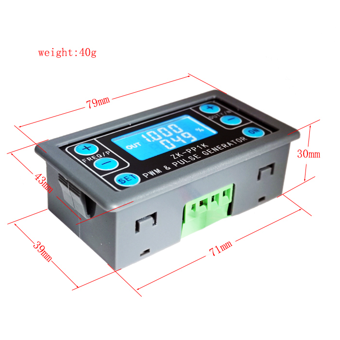
- Product size: 79mm*43mm*30mm
- Product Weight: 40g
Package Included:
- 1 x PWM Pulse Generator
3. Module Description:
3.1 Button Operation Instructions
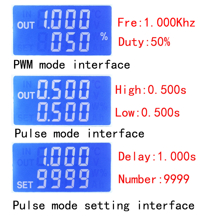
3.2 PWM Mode (display with % for PWM mode)
The factory default mode is PWM mode, FREQ+ and FREQ-key set frequency, DUTY+ and DUTY-button set duty cycle; short press ON button control signal output or stop, stop output is 0, the screen displays OUT mark as There is output, otherwise it stops output; the default factory frequency is 1KHZ and the duty cycle is 50%.
If you want to switch to PULSE mode, long press the SET button (more than 6 seconds), do not release, you will see the screen change, % disappears, it is PULSE mode.
3.3 PULSE Mode (No % on the right side of the display is PULSE mode)
The line above the LCD screen displays the positive pulse width time. The P+ and P- buttons set the parameter. The line below the LCD screen displays the negative pulse width time. The N+ and N- buttons set the parameter. Press the ON button to control the signal output or stop. When the output is stopped, the output is 0. The screen displays OUT for output, otherwise it stops output; the default factory positive pulse width is 0.5 seconds and the negative pulse width is 0.5 seconds.
Pulse number and delay time setting - In PULSE mode, press and hold the SET button for 2 seconds and then release, enter the pulse number and delay time setting interface, the screen displays SET, it will be turned off and cleared after entering. ;P+ and P- buttons set the delay time, N+ and N- buttons set the number of pulses, the factory default delay time is 0 seconds, the number of pulses is infinite (display ----); then press SET button 2 In seconds, it will automatically return to the pulse interface, press the ON button, after the delay setting time, start to issue the set number of pulses. If the number of pulses is sent, it will automatically output 0. If the period is not sent, pressing the ON button will turn off. The output pulse is turned off and cleared, and the set number of pulses is issued each time it is started. After the number of pulses is sent, the display 'OUT' automatically disappears.
3.4 Application Operation Examples
3.4.1 PWM output 20KHZ, 60% duty cycle: Select PWM mode, the frequency is set to 20.00, and the duty ratio is set to 060%.
3.4.2 The output is turned on for 0.6 seconds and turned off for 0.2 seconds. Infinite loop: select PULSE mode, the positive pulse width is set to 0.600, the negative pulse width is set to 0.200, the delay time is set to 0.000, and the number of pulses is set to --- -.
3.4.3 Power on or press the start button, delay 5 seconds, then the output is turned on for 0.6 seconds, off 0.2 seconds, infinite loop: select PULSE mode, positive pulse width is set to 0.600, negative pulse width is set to 0.200, delay The time is set to 5.000 and the number of pulses is set to ----.
3.4.4 Power on or press the start button, delay 5 seconds, then output high level 10ms low level 10ms pulse 100: select PULSE mode, positive pulse width is set to 0.010, negative pulse width is set to 0.010, delay The time is set to 5.000 and the number of pulses is set to 0100.
3.4.5 Power-on delay for 10 seconds, then permanently output signal: select PULSE mode, the positive pulse width is set to a number greater than 0, the negative pulse width is set to 0, the delay time is set to 10.00 seconds, and the pulse number is infinite. (----).
3.4.6 Other applications can explore or consult customer service
Attention: All setup parameters are not lost when it is power-off.