| Quantity | 3+ units | 10+ units | 30+ units | 50+ units | More |
|---|---|---|---|---|---|
| Price /Unit | $59.61 | $58.40 | $56.57 | $54.14 | Contact US |
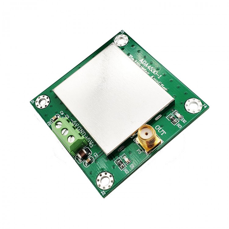
fA-Level Electrometer Transimpedance Amplifier For Weak Current Measurement ADA4530-1 (R=100MΩ)
Description:
The ADA4530-1 is a fA (10-15A) grade input bias current operational amplifier that can be used as an electrometer with integrated protective buffer. It also features low offset voltage, low offset offset, low voltage, and current noise required for low leakage applications.
It can be widely used in spectrophotometers, chromatographs, mass spectrometers, potentiostat and constant current coulomb methods, picoammeters, coulometers, photodiodes, transimpedance amplifiers for ion chambers and working electrode measurements, chemical sensors and capacitive sensors High impedance buffering.
Features:
- Power Supply: ±5V
- Input Current: 1pA to 3.4nA (R1=1GΩ)
- Output Voltage: ±3.4V
- Main chip rail-to-rail op amp, bias current is fA level, high accuracy
- Relationship Between Output Voltage (Vout) and Input Current (I): Vout=I*R1 (When R is 1GΩ by default, the input and output are in the same direction)
- Adopting typical trans-impedance IV circuit connection method, which can achieve the most accurate current measurement in principle at the current technology level
- Module Size: 50 x 50mm
- Location Hole: M3
- Hole Center Edge Distance: 4mm
Package Included:
- 1 x Electrometer Transimpedance Amplifier
Operation Instructions:
- Q1: Why are the input interfaces on the back of the board?
- A1: In order to minimize the distance between the input interface and the chip, a shorter wiring mode can reduce the leakage current on the circuit surface.
- Q2: Why are there three terminals for input?
- A2: The three terminals are signal, signal ground and shield ground respectively. It is recommended to use tri-axis cable to measure low current, which can effectively reduce leakage current.
- Q3: How to reduce the error for high resistance and low current measurement?
- A3: A shield can be used to reduce movement around the test platform and keep it quiet (especially when people move). You can use a protective layer and high-quality insulation materials to set up a test platform, and use a triaxial cable with low leakage. Please avoid cable bending, vibration, and excessive pressure test. Please test under a stable temperature and humidity environment.