| Quantity | 3+ units | 10+ units | 30+ units | 50+ units | More |
|---|---|---|---|---|---|
| Price /Unit | $131.64 | $128.96 | $124.93 | $119.55 | Contact US |
 Red Frame Music Tesla Coil 10 Mini 0-100W High Power Musical Coil Touchable Lightning Support Bluetooth Control
$39.37
Red Frame Music Tesla Coil 10 Mini 0-100W High Power Musical Coil Touchable Lightning Support Bluetooth Control
$39.37
 Black Frame Music Tesla Coil 10 Mini 0-100W High Power Musical Coil Touchable Lightning Support Bluetooth Control
$50.95
Black Frame Music Tesla Coil 10 Mini 0-100W High Power Musical Coil Touchable Lightning Support Bluetooth Control
$50.95
 Magnetic Levitation DIY Magnetic Levitation Module Assembled with Acrylic Shell 150G Load Limit
$39.68
Magnetic Levitation DIY Magnetic Levitation Module Assembled with Acrylic Shell 150G Load Limit
$39.68
Description:
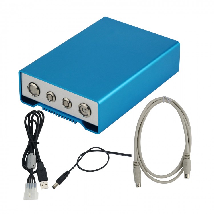
- The controller is used for automatic control of small loop antenna or electric GP antenna (electric screwdriver antenna), which is convenient and simple to operate. It can be connected with the Yeasu and ICOM radio stations to realize full-automatic adjustment. As long as you press the Tiandiao button on the radio station, you can automatically complete the antenna adjustment. It saves time and effort, and can also be controlled manually. As long as the Yeasu radio station can support FC-40 Tiandiao, this automatic controller can be used.
- The controller integrates a stepping motor driver with a maximum current of 2.5A, which is used to upgrade and modify the configuration parameters of the TF card, buzzer and led to indicate the working state, including start / stop and reset. The standing wave detection board has the function of radio station high standing wave protection during antenna adjustment.
- During full manual control, connect the standing wave detection board in series between the feeder of the radio and the antenna, and the control board is connected to the 13.8V DC power supply. The radio transmits with 100W in CW mode (Note: it can withstand power up to 100W in a short time to avoid the machine from being burnt due to misoperation). Press the start / stop button of the controller, and the orange LED will light up and start the adjustment. After the adjustment, the blue LED will light up, and the adjustment is successful, If the blue LED is not on, the adjustment fails. In the process of antenna adjustment, keep the radio in the continuous transmission state, and stop the radio transmission after the adjustment. Press the start / stop button again in the adjustment project to cancel the adjustment at any time.
- Firmware upgrade. When there is a new version of firmware, replace STM32 in the TF card Bin file (the file name of the upgrade file must be stm32.bin, otherwise it cannot be upgraded). Insert the TF card back, press and hold the reset button, and turn on the controller power switch. At this time, the controller automatically enters the firmware upgrade process. Wait for about ten seconds, LED1 flashes and hears the buzzer, indicating that the upgrade is successful. LED1 flashes at an interval of 0.5 seconds during the upgrade process, indicating that no TF card is inserted. Flashing at an interval of 0.1 seconds indicates that the upgrade failed or there is no upgraded file in the card or the file name is wrong.
- If the controller flashes regularly after being powered on, and the key fails, it indicates that there is a problem with the controller firmware. Please contact the maintenance department.
Description of configuration file in TF Card:
- Subdivision: subdivision, which corresponds to the subdivision value set on the stepping motor driver. Value range: 2-1024.
- Step1: when measuring the standing wave each time, the number of steps of the stepping motor is large, and the time to find the resonance point is short. If the value is too large, it will cross the resonance point, resulting in the failure to find the resonance point. Value range: 1-1024.
Roun1: speed per minute, stepping motor speed, value range 1-500.
Step 2: when looking for the resonance point, the standing wave is less than the threshold value, reduce the steps of each action of the motor, and the value range is 1-1024.
Roun2: when looking for the resonance point, the standing wave is less than the threshold value, and the motor speed is reduced. The value range is 1-500.
Bthreshold value: standing wave threshold. When the standing wave value is lower than this value, find the resonance point according to the values of step 2 and roun2. Value range: 1.1-9.9.
Step3: number of steps. Each time when looking for the resonance point, the motor will reverse the distance of step1 * Step3, and then officially look for the resonance point. Value range: 1-9999.
- Jog step: jog steps 1-1024.
- Jog round: jog speed, value range 1-500


")