| Quantity | 3+ units | 10+ units | 30+ units | 50+ units | More |
|---|---|---|---|---|---|
| Price /Unit | $48.20 | $47.21 | $45.74 | $43.77 | Contact US |
 G1009 10-inch Embedded HD Industrial Monitor 1024x768 Hook Mount TFT Display with BNC/VGA/AV/HDMI-compatible Ports
$109.57
G1009 10-inch Embedded HD Industrial Monitor 1024x768 Hook Mount TFT Display with BNC/VGA/AV/HDMI-compatible Ports
$109.57
 G121SN01 V3 Color Active Matrix LCD Display Panel Designed for Various Industrial Applications
$88.42
G121SN01 V3 Color Active Matrix LCD Display Panel Designed for Various Industrial Applications
$88.42
 RTU-307D NET-07D 8AI-8DI-8DO Data Acquisition Module IO Module (RS485+RS232) for Industrial Use
$76.89
RTU-307D NET-07D 8AI-8DI-8DO Data Acquisition Module IO Module (RS485+RS232) for Industrial Use
$76.89
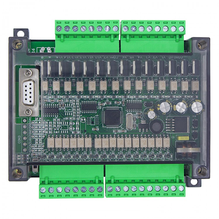
FX1N-30MT PLC Controller Programmable Logic Controller Direct Download Transistor Output With Shell
Advantages:
- 16 inputs 14 outputs
- Online monitoring
- Direct download
- NTC temperature measurement
- MT transistor type: Support pulse output. Only support DC24V load. Output current up to 1A
Features:
- Original chip
- Stable performance
- Online download
- Online monitoring
- Can be used in various industrial automation control
- Suitable for metallurgy, printing, chemicals, plastics, building materials, home furnishing, packaging, textiles, food
Specifications:
- Item name: Industrial controller board
- Model: FX1N-30MT
- Product number: 13200
- Output type: Transistor output
- Input point: 16 points
- Output point: 14 points
- Power supply voltage: 24V DC
- Output current: 1A
- Analog quantity input: Optional 3AD 0-10V/4-20MA/NTC 10K
- Analog quantity output: Optional 3AD 0-10V
- High-speed counting: 2-channel 3K
- Pulse output: 2-channel 3K
- Floating point: Not support
- Support Stepper motor: 2pcs
- Internal storage capacity: 8000 steps
- Download way: Direct download
- RS485 communications port: Optional
- For MODBUS: Optional
- Connect text screen: Support
- Connect touch screen: Support
- Programming software: For GX Developer or GX Works2
- Installation way: Fixed isolation column installation
Package Included:
- 1 x Set of PLC Controller
Instruction List:
Basic Sequence Commands:
LD: take
LDI: Take reverse
AND: and
ANI: and reverse
OR: or
ORI: or reverse
OUT: output
SET: set
RST: reset
ANB: Loop block and
0RB: loop block or
MPS: Push to stack
MRD: read stack
MPP: Unstack
INV: reverse
LDP: Take the rising edge of the pulse
LDF: Take the falling edge of the pulse
ANDP: and pulse rising edge
ANDF: and pulse falling edge
ORP: Or pulse rising edge
ORF: OR pulse falling edge
RET: return
PLS: rising edge pulse
PLF: Falling edge pulse
MC: Master
MCR: Master control reset
END: end
Step Instructions:
STL: Step ladder diagram
Procedure Flow Chart:
CJ: Conditional jump
CALL: subroutine call
SRET: Subroutine return
IRET: Interrupt return
EI: Open interrupt
DI: Close interrupt
FEND: End of main program
WDT: Watchdog timer refresh
FOR: starting point and number of loops
NEXT: the end of the loop
Send and Compare:
MOV: transfer
CML: Inverted transmission
XCH: Exchange
BCD: Binary conversion to BCD
BIN: Convert BCD code to binary
CMP: Comparison
ZCP: Interval comparison
FMOV: Multicast
SMOV: Bit transfer
BMOV: batch delivery
Arithmetic and Logical Operations:
ADD: Binary addition operation
SUB: Binary subtraction operation
MUL: Binary multiplication operation
DIV: Binary division operation
INC: Binary plus 1 operation
DEC: Binary minus 1 operation
WAND: Word Logic And
WOR: Word logical OR
WXOR: Word logic exclusive OR
NEG: Find two's complement
Bit Data Processing:
ZRST: Word shift left
DECO: Decoding
ENCO: Encoding
Cycle and Displacement:
SFTR: bit shift right
SFTL: bit shift left
SFWR: FIFO (first in first out) write
SFRD: FIFO (first in first out) read
High-Speed Processing:
REF: Input and output refresh
REFF: Input filter time adjustment
MTR: Matrix input
HSCS: Compare set (for high-speed counting)
HSCR: Comparison reset (for high-speed counting)
SPD: Pulse density
PLSY: Specified frequency pulse output
PWM: Pulse width modulation output
PLSR: With acceleration and deceleration pulse output
Convenient Instructions:
IST: State initialization
ABSD: Cam control (absolute)
INCD: Cam control (incremental)
ALT: Alternate output
RAMP: ramp signal
Peripheral I/O Device Port:
DSW: BCD digital switch input
SEGL: Seven-segment code time-sharing display
FROM: BFM read
TO: BFM write
Peripheral Equipment:
RS: Serial data transmission
PRUN: octal digit transmission (#)
ASCI: Convert hexadecimal number to ASCI code
HEX: Convert ASCI code to hexadecimal number
CCD: Check
VRRD: Potentiometer variable input
VRSC: Potentiometer variable interval
PID: PID calculation
Positioning:
ABS: ABS current value read
ZRN: Return to origin
PLSV: Variable speed pulse output
DRVI: Relative position control
DRVA: Absolute position control
Clock Operation:
TCMP: Clock data comparison
TZCP: Clock data interval comparison
TADD: Clock data addition
TSUB: Clock data subtraction
TRD: Clock data read
TWR: Clock data write
HOUR: Chronograph
Contact Comparison:
LD: (S1)=(S2) when the starting contact is on
LD>: (S1)>(S2) when the starting contact is on
LD<: (S1) <(S2) when the starting contact is on
LD<>: (S1)<>(S2) when the starting contact is on
LD≦: (S1)≦(S2) When the starting contact is on
LD≥: (S1)≥(S2) when the starting contact is on
AND=: (S1)=(S2) when the series contact is on
AND>: (S1)>(S2) when the series contact is on
AND<: (S1)<(S2) when the series contact is on
AND<>: (S1)<>(S2) when the series contact is on
AND≤: When (S1)≤(S2), the series contacts are connected
AND≥: When (S1)≥(S2), the series contact is on
OR=: (S1)=(S2) when the parallel contacts are connected
OR>: (S1)>(S2), the parallel contacts are connected
OR<: When (S1)<(S2), the parallel contacts are connected
OR<>: (S1)<>(S2), the parallel contacts are connected
OR≤: When (S1)≤(S2), the parallel contacts are connected
OR≥: When (S1)≥(S2), the parallel contacts are connected
Special Component Description:
M8000: RUN monitoring (always open during RUN)
M8002: Initialization pulse (normally open scan cycle flag)
M8004: Error prompt (PLC error)
M8012: 100ms clock (oscillate with 100ms period)
M8014: 1 min clock (oscillate with 1 min period)
M8021: Dislocation mark
M8029: instruction execution end
M8034: disable output
M8001: RUN monitoring (normally closed during RUN)
M8003: Initialization pulse (normally closed scan cycle flag)
M8011: 10ms clock (oscillate with 10ms period)
M8013: 1s clock (oscillates in 1S period)
M8020: Zero mark (operation mark for application instructions)
M8022: Carry flag
M8033: Memory storage
Summary of Soft Element Function:
Auxiliary Relay:
General use: M0-M383, 384 points
Keep use: M384-M1535, 1152 points
Special use: M8000-M8255, 256 points
Status Register:
Initial state: S0-S9, 10 points
General status: S10-S127, 118 points
Save area: S128-S899, 772 points
Timer:
100MS: T0-T199, 200 points
10MS: T200-T245, 46 points
1MS cumulative type: T246-T249, 4 points
100MS cumulative type: T250-T256, 6 points
Counter:
16-bit increment (general use): C0-C15, 16 points
16-bit increment (for holding): C16-C199, 184 points
32-bit reversible (general use): C200-C219, 20 points
32-bit reversible (for holding): C220-C234, 15 points
32-bit reversible (for high-speed retention): C235-C255, 8 points
Data Register:
16-bit general use: D0-D127, 128 points
16-bit retention: D128-D2300, 2172 points
16-bit special use: D8000-D8255, 20 points
For 16-bit indexing: V0-V7 Z0-Z7, 15 points
Nested Pointers:
For skip subroutine, branch: P0-P127, 128 points
Main control: N0-N7, 8 points
Constant:
Decimal (K): 16-32768 to +32767, 32-bit
Hexadecimal (H): 16 bits: 0~FFFFH, 32 bits: 0~FFFFFFFFH


")


")

")