| Quantity | 3+ units | 10+ units | 30+ units | 50+ units | More |
|---|---|---|---|---|---|
| Price /Unit | $46.45 | $45.50 | $44.08 | $42.19 | Contact US |
 G1009 10-inch Embedded HD Industrial Monitor 1024x768 Hook Mount TFT Display with BNC/VGA/AV/HDMI-compatible Ports
$109.57
G1009 10-inch Embedded HD Industrial Monitor 1024x768 Hook Mount TFT Display with BNC/VGA/AV/HDMI-compatible Ports
$109.57
 G121SN01 V3 Color Active Matrix LCD Display Panel Designed for Various Industrial Applications
$88.42
G121SN01 V3 Color Active Matrix LCD Display Panel Designed for Various Industrial Applications
$88.42
 RTU-307D NET-07D 8AI-8DI-8DO Data Acquisition Module IO Module (RS485+RS232) for Industrial Use
$76.89
RTU-307D NET-07D 8AI-8DI-8DO Data Acquisition Module IO Module (RS485+RS232) for Industrial Use
$76.89
FX1N-30MR PLC Controller Board Programmable Logic Controller Direct Download Relay Output With Shell
Advantages:
- 16 inputs 14 outputs
- Online monitoring
- Direct download
- NTC temperature measurement
- MR Relay: Not support pulse. Can connect AC220 or DC 24V load. Output current up to 5A
Features:
- Original chip
- Stable performance
- Online download
- Online monitoring
- Can be used in various industrial automation control
- Suitable for metallurgy, printing, chemicals, plastics, building materials, home furnishing, packaging, textiles, food
Specifications:
- Item name: Industrial controller board
- Model: FX1N-30MR
- Product number: 12600
- Output type: Relay output
- Input point: 16 points
- Output point: 14 points
- Power supply voltage: 24V DC
- Output current: 5A
- Analog quantity input: Optional 3AD 0-10V/4-20MA/NTC 10K
- Analog quantity output: Optional 2DA 0-10V
- High-speed counting: 2-channel 3K
- Pulse output: None
- Floating point: Not support
- Stepper motor: Not support
- Internal storage capacity: 8000 steps
- Download way: Direct download
- RS485 communications port: Optional
- For MODBUS: Optional
- Connect text screen: Support
- Connect touch screen: Support
- Programming software: For GX Developer or GX Works2
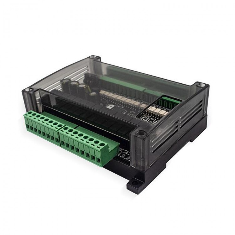
- Installation way: Fixed isolation column installation
Package Included:
- 1 x Set of PLC Controller
Instruction List
Basic Sequence Commands:
LD: take
LDI: Take reverse
AND: and
ANI: and reverse
OR: or
ORI: or reverse
OUT: output
SET: set
RST: reset
ANB: Loop block and
0RB: loop block or
MPS: Push to stack
MRD: read stack
MPP: Unstack
INV: reverse
LDP: Take the rising edge of the pulse
LDF: Take the falling edge of the pulse
ANDP: and pulse rising edge
ANDF: and pulse falling edge
ORP: Or pulse rising edge
ORF: OR pulse falling edge
RET: return
PLS: rising edge pulse
PLF: Falling edge pulse
MC: Master
MCR: Master control reset
END: end
Step Instructions:
STL: Step ladder diagram
Procedure Flow Chart:
CJ: Conditional jump
CALL: subroutine call
SRET: Subroutine return
IRET: Interrupt return
EI: Open interrupt
DI: Close interrupt
FEND: End of main program
WDT: Watchdog timer refresh
FOR: starting point and number of loops
NEXT: the end of the loop
Send and Compare:
MOV: transfer
CML: Inverted transmission
XCH: Exchange
BCD: Binary conversion to BCD
BIN: Convert BCD code to binary
CMP: Comparison
ZCP: Interval comparison
FMOV: Multicast
SMOV: Bit transfer
BMOV: batch delivery
Arithmetic and Logical Operations:
ADD: Binary addition operation
SUB: Binary subtraction operation
MUL: Binary multiplication operation
DIV: Binary division operation
INC: Binary plus 1 operation
DEC: Binary minus 1 operation
WAND: Word Logic And
WOR: Word logical OR
WXOR: Word logic exclusive OR
NEG: Find two's complement
Bit Data Processing:
ZRST: Word shift left
DECO: Decoding
ENCO: Encoding
Cycle and Displacement:
SFTR: bit shift right
SFTL: bit shift left
SFWR: FIFO (first in first out) write
SFRD: FIFO (first in first out) read
High-Speed Processing:
REF: Input and output refresh
REFF: Input filter time adjustment
MTR: Matrix input
HSCS: Compare set (for high-speed counting)
HSCR: Comparison reset (for high-speed counting)
SPD: Pulse density
PLSY: Specified frequency pulse output
PWM: Pulse width modulation output
PLSR: With acceleration and deceleration pulse output
Convenient Instructions:
IST: State initialization
ABSD: Cam control (absolute)
INCD: Cam control (incremental)
ALT: Alternate output
RAMP: ramp signal
Peripheral I/O Device Port:
DSW: BCD digital switch input
SEGL: Seven-segment code time-sharing display
FROM: BFM read
TO: BFM write
Peripheral Equipment:
RS: Serial data transmission
PRUN: octal digit transmission (#)
ASCI: Convert hexadecimal number to ASCI code
HEX: Convert ASCI code to hexadecimal number
CCD: Check
VRRD: Potentiometer variable input
VRSC: Potentiometer variable interval
PID: PID calculation
Positioning:
ABS: ABS current value read
ZRN: Return to origin
PLSV: Variable speed pulse output
DRVI: Relative position control
DRVA: Absolute position control
Clock Operation:
TCMP: Clock data comparison
TZCP: Clock data interval comparison
TADD: Clock data addition
TSUB: Clock data subtraction
TRD: Clock data read
TWR: Clock data write
HOUR: Chronograph
Contact Comparison:
LD: (S1)=(S2) when the starting contact is on
LD>: (S1)>(S2) when the starting contact is on
LD<: (S1) <(S2) when the starting contact is on
LD<>: (S1)<>(S2) when the starting contact is on
LD≦: (S1)≦(S2) When the starting contact is on
LD≥: (S1)≥(S2) when the starting contact is on
AND=: (S1)=(S2) when the series contact is on
AND>: (S1)>(S2) when the series contact is on
AND<: (S1)<(S2) when the series contact is on
AND<>: (S1)<>(S2) when the series contact is on
AND≤: When (S1)≤(S2), the series contacts are connected
AND≥: When (S1)≥(S2), the series contact is on
OR=: (S1)=(S2) when the parallel contacts are connected
OR>: (S1)>(S2), the parallel contacts are connected
OR<: When (S1)<(S2), the parallel contacts are connected
OR<>: (S1)<>(S2), the parallel contacts are connected
OR≤: When (S1)≤(S2), the parallel contacts are connected
OR≥: When (S1)≥(S2), the parallel contacts are connected
Special Component Description:
M8000: RUN monitoring (always open during RUN)
M8002: Initialization pulse (normally open scan cycle flag)
M8004: Error prompt (PLC error)
M8012: 100ms clock (oscillate with 100ms period)
M8014: 1 min clock (oscillate with 1 min period)
M8021: Dislocation mark
M8029: instruction execution end
M8034: disable output
M8001: RUN monitoring (normally closed during RUN)
M8003: Initialization pulse (normally closed scan cycle flag)
M8011: 10ms clock (oscillate with 10ms period)
M8013: 1s clock (oscillates in 1S period)
M8020: Zero mark (operation mark for application instructions)
M8022: Carry flag
M8033: Memory storage
Summary of Soft Element Function:
Auxiliary Relay:
General use: M0-M383, 384 points
Keep use: M384-M1535, 1152 points
Special use: M8000-M8255, 256 points
Status Register:
Initial state: S0-S9, 10 points
General status: S10-S127, 118 points
Save area: S128-S899, 772 points
Timer:
100MS: T0-T199, 200 points
10MS: T200-T245, 46 points
1MS cumulative type: T246-T249, 4 points
100MS cumulative type: T250-T256, 6 points
Counter:
16-bit increment (general use): C0-C15, 16 points
16-bit increment (for holding): C16-C199, 184 points
32-bit reversible (general use): C200-C219, 20 points
32-bit reversible (for holding): C220-C234, 15 points
32-bit reversible (for high-speed retention): C235-C255, 8 points
Data Register:
16-bit general use: D0-D127, 128 points
16-bit retention: D128-D2300, 2172 points
16-bit special use: D8000-D8255, 20 points
For 16-bit indexing: V0-V7 Z0-Z7, 15 points
Nested Pointers:
For skip subroutine, branch: P0-P127, 128 points
Main control: N0-N7, 8 points
Constant:
Decimal (K): 16-32768 to +32767, 32-bit
Hexadecimal (H): 16 bits: 0~FFFFH, 32 bits: 0~FFFFFFFFH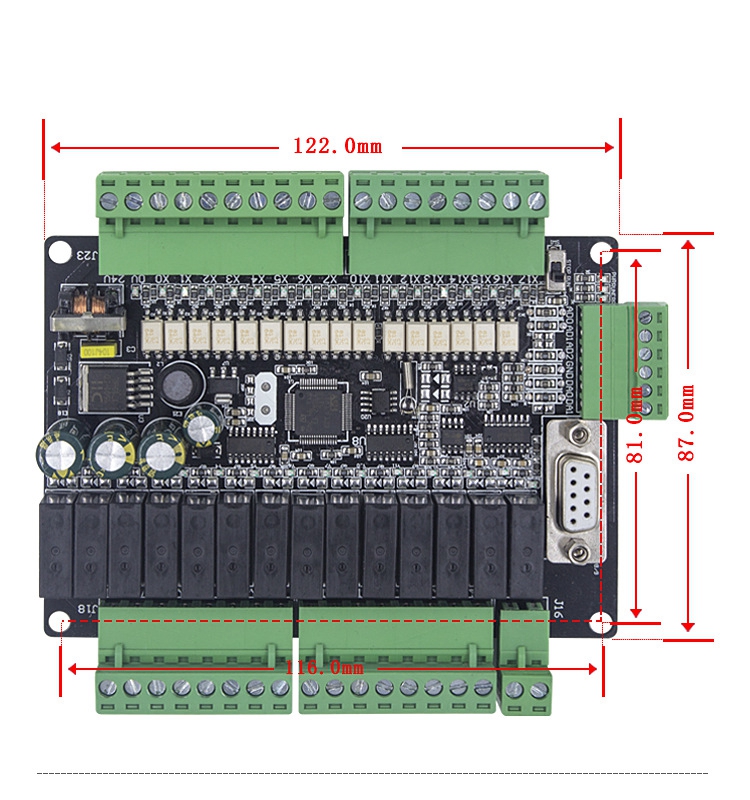
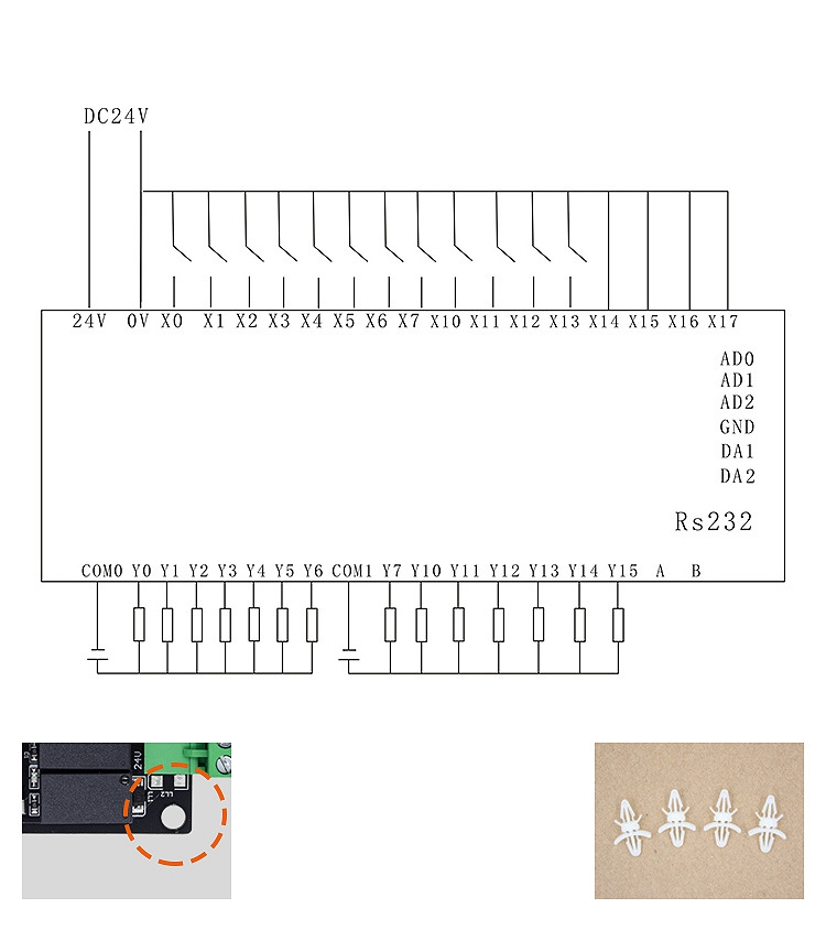
How to Fix?
The
installation method of PLC: The installation method used is to fix
rubber particles on the drill hole. Each PLC board has holes on the four
corners for installation. Each board is equipped with 4pcs PC board
isolation columns.


")
")


")