| Quantity | 3+ units | 10+ units | 30+ units | 50+ units | More |
|---|---|---|---|---|---|
| Price /Unit | $43.36 | $42.47 | $41.14 | $39.37 | Contact US |
 G1009 10-inch Embedded HD Industrial Monitor 1024x768 Hook Mount TFT Display with BNC/VGA/AV/HDMI-compatible Ports
$109.57
G1009 10-inch Embedded HD Industrial Monitor 1024x768 Hook Mount TFT Display with BNC/VGA/AV/HDMI-compatible Ports
$109.57
 G121SN01 V3 Color Active Matrix LCD Display Panel Designed for Various Industrial Applications
$88.42
G121SN01 V3 Color Active Matrix LCD Display Panel Designed for Various Industrial Applications
$88.42
 RTU-307D NET-07D 8AI-8DI-8DO Data Acquisition Module IO Module (RS485+RS232) for Industrial Use
$76.89
RTU-307D NET-07D 8AI-8DI-8DO Data Acquisition Module IO Module (RS485+RS232) for Industrial Use
$76.89
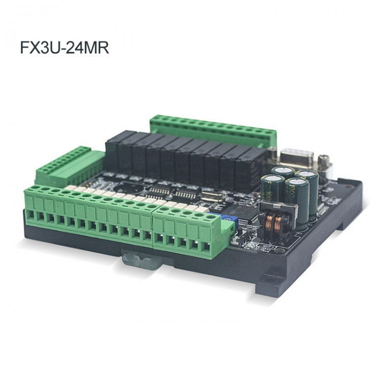
For Mitsubishi PLC Programmable Logic Controller FX3U-24MR High-Speed Input Output w/ 6 Analog Inputs
Features:
- FX3U-24MR industrial control board
- Original chip
- Stable performance
- Online Download
- Online monitoring
- MR Relay: Not support pulse. Can connect AC220 or DC 24V load. Output current up to 5A
- Can be used in various industrial automation control
- Suitable for metallurgy, printing, chemicals, plastics, building materials, home furnishing, packaging, textiles, food
Product Parameters:
- Product name: industrial control board
- Product model: FX3U-24MR
- Product number: 08900
- Output type: Relay output
- Input points: 14 points
- Output points: 10 points
- Supply voltage: 24V DC
- Output current: 5A
- Analog input: 6AD
- Analog output: 2DA
- High-speed counting: 6 channels 3K. Optional 6 channels 60K
- Pulse output: None
- Floating point: support
- Stepper motor: not supported
- Memory capacity: 8000 steps
- Download method: Direct download
- RS485 communication port: optional
- For MODBUS: optional
- Connect text screen: support
- Connect the touch screen: support
- Programming software: For GX Developer or GX Works2
- Installation method: fixed isolation column installation
Soft Element:
- Intermediate relay M: M0-M3071, power-down storage range can be set M0-M1023
- Step point S: S0-1023, power-down saving range can be set to S0-S1023
- 100MS timer: T0-T199, accumulative power-down save T184-T199
- 10MS timer: T200-T249, accumulative power-off save T246-T249
- 1MS timer: T250-T383, of which T250-255 is cumulative
- 16-bit counter: C0-C199, save C100-199 when power off
- 32-bit counter: C200-C219, save C220-C234 when power off
- 32-bit high-speed counter:
C235-255; C235-240 is a single-phase counter without frequency multiplication;
C241-240 is a single-phase counter, 2 times the frequency;
C247-249 is a two-phase counter without frequency multiplication;
C250-252 is a two-phase counter, 2 times the frequency;
C253- is a two-phase counter, 4 times the frequency;
- Register D: D0-D7999, the saving range can be set to D0-7999 after power-off,
- Indirect addressing pointer V, Z: V0-7, Z0-7
- P subroutine jump number: P0-63
- I Interrupt: X0-5 external interrupt. Timer interrupt (1MS as a unit). The counter is interrupted.
- Special M element: M8000 is normally closed when running, M8002 is power-on pulse, M8011 is 10Ms pulse, M8012 is 100Ms pulse, M8013 is 1s pulse, and M8014 is minute pulse.
Instruction List:
Basic instructions:
LD: Normally open contact at the start of operation
LDI: Normally closed contact at the start of operation
LDP: Rising edge detection operation starts
LDF: Falling edge detection operation starts
AND: series normally open contact
ANI: Series normally closed contact
ANDP: Series connection detected on rising edge
ANDF: Falling edge detection of series connection
OR: Parallel normally open contacts
ORI: Parallel normally closed contacts
ORP: parallel connection detected by rising edge
ORF: Falling edge detection parallel connection
ANB: Series connection between circuit blocks
ORB: parallel connection between circuit blocks
OUT: Coil output drive
SET: keep the coil action
RST: Release the coil operation hold
PLS: Coil rising edge output
PLF: Coil falling edge output
ALT: alternate output
MC: Coil for common string connection point
MCR: Common contact release command
MPS: Operational storage
MRD: storage read
MPP: memory read and reset
INV: Invert the result of the operation
END: end of program
STL: start of step ladder diagram
RET: End of step ladder diagram
CALL: call subroutine
SRET: Subroutine return
Procedure Flow Chart:
CJ: Conditional jump
CALL: subroutine call
SRET: Subroutine return
FEND: End of main program
Send and Compare:
CMP: Comparison
ZCP: Regional comparison
MOV: transfer
CML: Reverse transmission
BMOV: send together
FMOV: Multicast
XCH: Exchange
BCD: BCD conversion
BIN: BIN conversion
Four Logical Operations:
ADD: BIN addition
SUB: BIN subtraction
MUL: BIN multiplication
DIV: BIN division
INC: BIN plus 1
DEC: BIN minus 1
WAND: logical word and
WPR: logical word or
WXOR: logical word exclusive OR
NEG: complement
Cycle Displacement:
ROR: right shift cycle
ROL: Shift left loop
RCR: right shift
RCL: Left shift
SFTL: bit shift left
SFTR: bit shift right
Special Components Instruction:
M8000: Normally closed during operation
M8002: Power-on pulse
M8011: 10Ms pulse
M8012: 100Ms pulse
M8013: 1s pulse
M8014: is the minute pulse
ZRST: Batch reset
MEAN: Average
FLT: BIN, integer → 2, hexadecimal floating point number conversion
GRY: BIN, integer → gray code conversion
GBIN: Gray code → BIN, integer
DHSCS: High-speed comparison set
DHSCR: High-speed comparison reset
SPD: Pulse density, pulse width (pulse interval time) can also be measured
PLSY: Pulse output
PLSV: Pulse output with direction control
PWM: Pulse width modulation, 0-32767us
PLSR: Pulse output with acceleration and deceleration
DRVA: Absolute position control
DRVI: Relative position control
ABSD: Cam control (absolute method)
RS: Serial data transmission
ASCI: HEX-ASCII conversion
HEX: ASCII-HEX conversion
CCD: check code
PID: PID calculation
SEGD: BCD to 7-segment digital tube
ECMP: Comparison of binary floating-point numbers
EZCP: Interval comparison of binary floating point numbers
EBIN: decimal floating point number-2, conversion of decimal floating point number
EADD: Addition of binary floating-point numbers
ESUB: binary floating-point number subtraction
EMUL: Binary floating point number multiplication
EDIV: Division of binary floating-point numbers
INT: Binary floating point number -BIN, integer conversion
SIN: floating-point number SIN operation
TAN: Floating point number TAN operation
COS: Floating point COS operation
ASIN: floating-point number SIN-1 operation
EXP: binary floating point exponential operation
LOGE: natural logarithm operation of binary floating-point numbers
LOGE10: Commonly used logarithmic operations of binary floating-point numbers
SWAP: Up and down byte conversion
SER: data search
ALT: alternate output
RAMP: ramp signal
BON: ON bit judgment
SUM: ON digits
ANS: Alarm set
ANR: Alarm reset
HOUR: Chronograph
TCMP: Clock data comparison
TRD: Clock data read
TWR: clock data write
LD=: (S1=(S2)
LD>: (S1)>(S2)
LD<: (S1)<(S2)
LD◇: (S1)≠(S2)
LD≤: (S1)≤(S2)
LD≥: (S1)≥(S2)
AND=: (S1=(S2)
AND>: (S1)>(S2)
AND<: (S1)<(S2)
AND◇: (S1)≠S2)
AND≤: (S1)≤(S2)
AND≥: (S1)≥(S2)
OR=: (S1=(S2)
OR>: (S1)>(S2)
OR<: (S1)<(S2)
OR◇: (S1)≠(S2)
OR≤: (S1)≤(S2)
OR≥: (S1)≥(S2)
Package Included:
- 1 x PLC Controller
Note:
- It is the version only with bare board. If you need a base, a shell, RS485 function, or a clock, please contact us to pay extra money when purchasing.
- Programming cable is not included. Please purchase separately.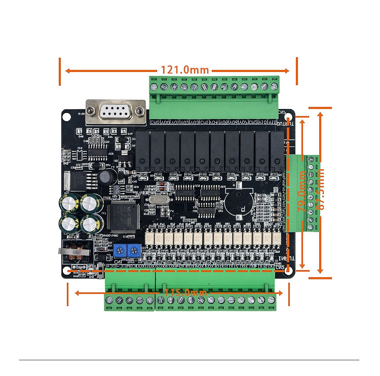
Wiring Diagram:
1. DC-: The power input is connected to the negative pole of the 24V switching power supply
2. DC+: The power input is connected to the positive pole of the 24V switching power supply
3. COM: input common terminal, low level
4. X0~X15 inputs are all active low and can be connected to NPN series sensors
5. X0~X5 can be used as high-speed counters. The default is up to 12K, optional 100K, supports 3 AB encoders and C251, etc.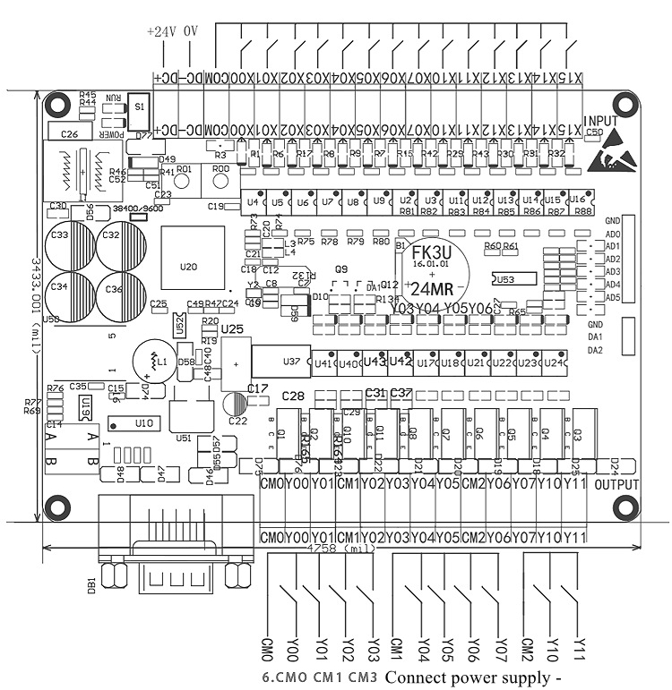
How To Fix:
The installation method of the panel PLC: The installation method of fixed rubber particles on the drilling hole is used. Each PLC board has holes on the four corners for fixing installation holes, and each board is equipped with 4 PLC board isolation columns.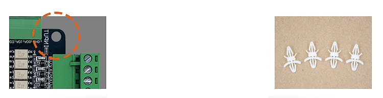
Application Example:


")
 & 7\" HMI Display 12DI 8DO")

 & 7\" HMI Display 12DI 8DO")


