| Quantity | 3+ units | 10+ units | 30+ units | 50+ units | More |
|---|---|---|---|---|---|
| Price /Unit | $37.15 | $36.39 | $35.26 | $33.74 | Contact US |
 Finished HiFi Preamplifier Board DIY Audio Amplifier Board Replacement for Marantz HDAM Classic Preamplifier
$32.62
Finished HiFi Preamplifier Board DIY Audio Amplifier Board Replacement for Marantz HDAM Classic Preamplifier
$32.62
 Line Magnetic Audio LM-508IA 48W+48W Tube Amplifier Integrated Amplifier Tube Amp with Two VU Meters
$2,624.45
Line Magnetic Audio LM-508IA 48W+48W Tube Amplifier Integrated Amplifier Tube Amp with Two VU Meters
$2,624.45
 2x80W HiFi Digital Power Amplifier Board V1.6 Class D Amplifier Board for MERUS MA12070 with Toggle Switch
$33.44
2x80W HiFi Digital Power Amplifier Board V1.6 Class D Amplifier Board for MERUS MA12070 with Toggle Switch
$33.44
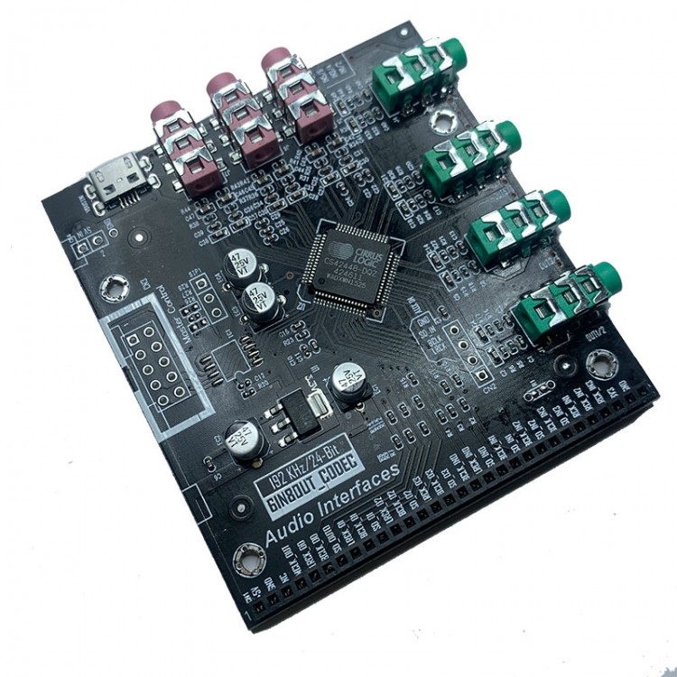
High Performance Single CS42448 6 In 8 Out Decoder Board Support SPI and I2C Communication
Description:
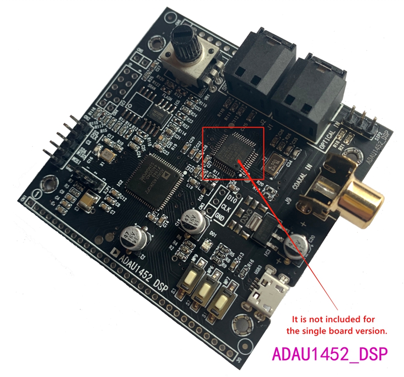
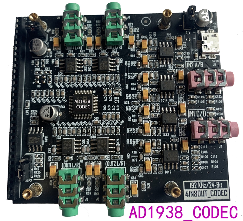
- The new version of the DSP board is equipped with MCU_STM32F103C8T6 (In view of the recent chip boom, there is no patch on the actual shipment board, the MCU itself has no program, and the board can still work normally without it.). AD1938_CODEC decoder board added a single-chip board for soft control, which can set the sampling rate and audio interface type.
- On-board routines provide input / output IIS / SPDIF (off fiber / coaxial selection) interface (Single ADU1450-DSP board do not support SPDIF);
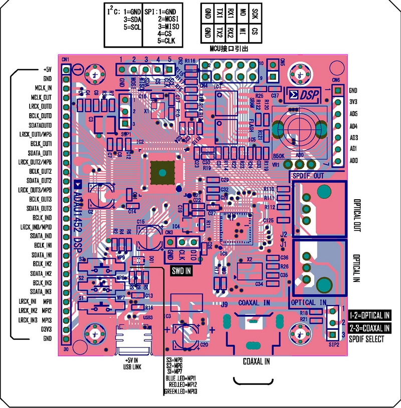
- For ADAU1452 series routines, the configuration page can freely select the communication mode (SPI or I2C) for SIGMASTUDIO and the target board. The SPI mode address is SPI 0x1 ADR0, I2C address is I2C 0x16 (118), and E2Prom is SPI 0x1 ADR0, which does not need to be changed.
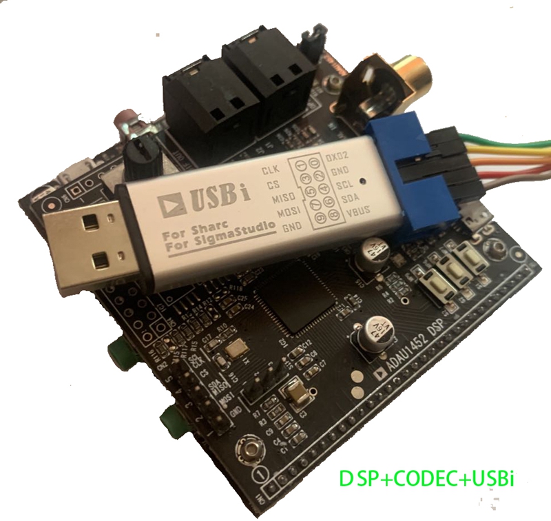
- Definition of the link mode between USBi and target board (ADAU1452dsp board):
SPI communication mode: 1/3/5/7/9 (CLK/CS/MISO/MOSI/GND) of the USBi terminal of the simulator corresponds to 5/4/3/2/1 of the CN2 of the target board (ADAU1452 dsp board), which is just in order.
I2C communication mode: 2/4/6 (GND/SCL/SDA) of the USBi terminal of the simulator corresponds to 1/5/3 of the CN2 of the target board (ADAU1452 dsp board).
- The SIP1 on the target board is basically useless as a self-starting jumper. It is not necessary to cancel the self-starting at all, so you can throw away the jumper cap and do not plug it into the 12 terminal.
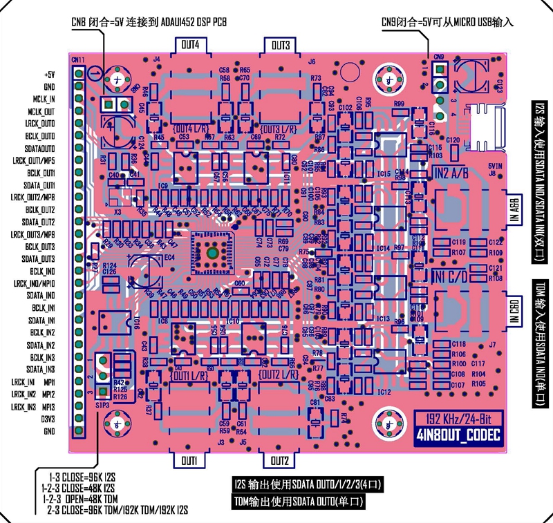
- The factory test routine is: ADAU1452 power distribution routine 192tdm.dspproj. The supporting AD1938 defaults to 192K/TDM audio transmission, with 4 channels in and 8 channels out. If you need to change the sampling rate and audio interface mode, you can refer to the description of the AD1938 board jumper, otherwise the sound will not be normal.
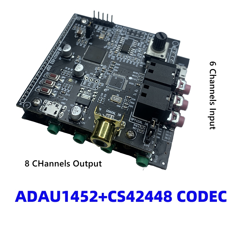
- Beginners suggest equipping the CODEC decoding of CS42448, supporting 6-channel input and 8-channel output, with a separate routine supporting, and the factory routine is 1452_ cs42448_ 192.dspproj, which has higher indicators, simple lines, high stability and support 48-192 sampling rate. What’s more, there is no need to switch configurations but concentrate on debugging DSP.
Instruction:
- The factory setting is 192K_TDM format, OUT3 / OUT4 are pass-through interfaces, and OUT1 / OUT2 are stereo 2 mode output interfaces.
- S1 for input selection; blue light flashes for SPDIF input, red for IN2 analog input. Green for IN1 analog input.
- S2 for preset EQ switching with total of 10 EQ presets.
- S3 for super bass switch, which is useful in electronic crossover subwoofer channel, open by default.
- Three-color LEDs indicate input channels and working status blinking;
- One STM32 single-chip microcomputer is reserved on the board. You can choose to use a single-chip microcomputer to control the DSP and leave a USB / uart / spi port.
Package Included:
- 1 x CS42448 6 In 8 Out Decoder Board