| Quantity | 3+ units | 10+ units | 30+ units | 50+ units | More |
|---|---|---|---|---|---|
| Price /Unit | $202.02 | $197.89 | $191.71 | $183.46 | Contact US |
 C-200T 3-Axis FPV Gimbal 200g Payload High Torque Brushless Motor Orthogonal Mechanical Stabilization FPV PTZ
$181.75
C-200T 3-Axis FPV Gimbal 200g Payload High Torque Brushless Motor Orthogonal Mechanical Stabilization FPV PTZ
$181.75
 C-40D Horizontal 2-Axis FPV Gimbal Mechanical Stabilization Structure High Torque Brushless Motor FPV PTZ
$114.79
C-40D Horizontal 2-Axis FPV Gimbal Mechanical Stabilization Structure High Torque Brushless Motor FPV PTZ
$114.79
 C-40T 3-Axis FPV Gimbal 40g Payload High Torque Brushless Motor Stabilizing PTZ Support for Headtracker
$164.02
C-40T 3-Axis FPV Gimbal 40g Payload High Torque Brushless Motor Stabilizing PTZ Support for Headtracker
$164.02
MFD MINI AAT Automatic Antenna Tracker High Quality Tracking Gimbal for Long Range System Model UAV Antenna
Description:
- The MyFlyDream Mini CrossbowMini AAT is designed for unmanned aerial vehicle (UAV) antenna systems, with the goal of providing comprehensive high gain signal reception capabilities. In order to achieve better signal reception quality, we hope to use high gain receiving antennas, but high gain antennas often come with narrow effective angles. The design of MFD Crossbow AAT is to solve the problem of directional antennas difficult to maintain at the optimal transmitting and receiving angle during UAV flight.
- CrossbowMini AAT work requires obtaining the longitude, latitude, and altitude of the tracked target (drone), and we provide several solutions for this, including:
1. Transmission of tracked target information through wireless analog video links. We need to install our TeleFlyPro tracking module (not included) or use our MFD AP/MFD Crosshair AP flight control on the drone.
2. Some high-definition images come with serial communication, and TeleFlyPro modules can be installed on the aircraft to transmit tracking data to Crossbow AAT through the serial port.
3. Use the MAVLink protocol to transmit drone information through a digital radio station. If the user system already includes a data radio station and flight control that supports the MAVLink protocol, we only need to share one TX line of the data radio station to Crossbow AAT to achieve tracking.
Installation and Wiring:
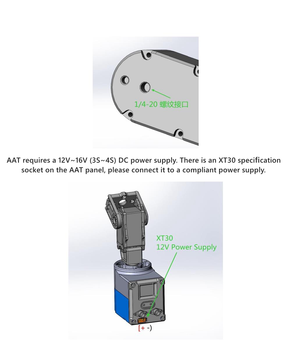
- There is a standard 1/4-20 tripod threaded interface at the bottom of the pan head. Please purchase a sturdy and reliable tripod and install the AAT onto the quick assembly board, ensuring that the stop protrusion on the tripod quick assembly board enters the corresponding stop hole at the bottom of the AAT.
- AAT requires a 12V~16V (3S~4S) DC power supply. There is an XT30 specification socket on the AAT panel, please connect it to a compliant power supply.
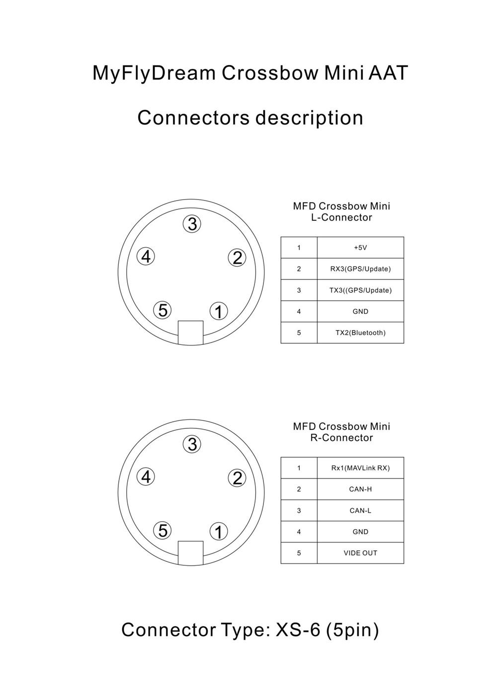
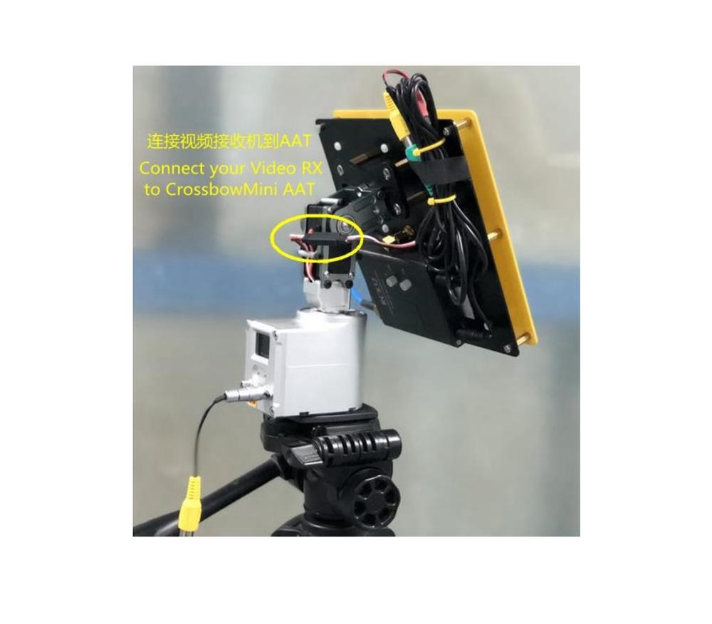
- Please firmly install your antenna onto the AAT antenna mounting bracket. Please try to avoid antennas containing ferromagnetic materials to avoid affecting the normal operation of the built-in compass of AAT. If possible, please try to use non-magnetic materials such as stainless steel screws and aluminum. Please connect the analog video receiver to the 3-pin socket on the back of the PTZ servo. The wiring definition of this socket is:
White: analog audio input
Red: 12V ~ 16V power supply ( same voltage as the PTZ power supply)
Black: ground
- There are two aircraft female socket on the top panel, left and right. The left socket is used to connect to external GPS, or upgrade firmware, etc. The socket on the right can output video signals or connect multiple machines through the CAN-BUS bus.
Please insert the accessory cable with RCA socket into the right socket.
The video signal from the video receiver will ultimately be output through the yellow RCA video output socket, which can be connected to an external display screen or video glasses for viewing.
- After checking the wiring, ensure that the tripod is secure and power on the PTZ for testing. Under normal circumstances, the tilt angle of the PTZ will return to 0 degrees horizontal (pointing towards the horizon), and the antenna will be pointing straight ahead. The screen on the panel will display the following information:
Batch/GPS alternation: displays the current power supply voltage of the PTZ and the number of onboard GPS satellites, respectively.
Dist: The current distance from the UVA to home. N/A indicates unavailable.
Alt: The current UVA relative height to home. N/A indicates unavailable.
Azim: The current azimuth angle of the UVA relative to home. N/A indicates unavailable.
VLink/DLink: 80% of the current downlink signal quality. Display as VLink or DLink based on whether the video or data link is currently used.
Dir: displays the azimuth angle of the current PTZ base alignment.
- When both the aircraft and the PTZ are powered on, the video output port of the PTZ connected to the display screen should display the image of the onboard camera. And the VLink on the screen will display the signal link quality. If VLink displays a signal strength of 0, please check if the flight control has been set to VBI encoded V2 version.
Outfield Using Steps:
- The aircraft and PTZ are powered on. Confirm if the signal quality displayed on the VLink of the PTZ screen is 0.
- When the number of satellites is sufficient, such as 8 or more, the flight control will execute the setup operation. At this point, if communication is normal, the small screen of the PTZ will display "SetHome" and initialize the location of the home.
- You can also briefly press the button on the right to set home for the PTZ.
- After the plane leaves 10 meters away, the PTZ will start automatic tracking.
Menu interface:
- Yaw Trim: Correct the degree of deviation in the tracking direction of the PTZ. Press the right button repeatedly to modify the value, ranging from -15 to+15. Negative numbers indicate adjusting the tracking antenna to the left, while positive numbers indicate adjusting the tracking antenna to the right.
- CalCompass: After execution, the screen displays a 10 second countdown. Rotate the entire AAT horizontally for at least one revolution to calibrate the internal magnetic compass.
- CompassMod magnetic compass usage:
OnlyPowerOn: Use a magnetic compass only once during initial power on
Always: Always use a magnetic compass
Never: Never use a magnetic compass, manually facing north
Exit
- Baudrate: Baud of data transmission interface, or communication Baud of external GPS/magnetic compass
Baud Rate Title Bar
115200
57600
38400
19200
9600
4800
2400
1200
Exit
- CalPitch: Calibrate pitch direction angle
UP: Adjust the PTZ elevation to increase
DOWN: Adjust the PTZ elevation to decrease
REC 90 DEG: Record the 90 degree elevation position of the PTZ
REC 0 DEG: Record the 0 degree elevation position of the PTZ
SAVE
EXIT
The steps for PTZ calibration: Use the UP/DOWN option to move the PTZ to a 90 degree head up position, and then execute REC 90 DEG to save this position setting. Use the UP/DOWN option to move the PTZ to the 0 degree horizontal position, and then execute REC 0 DEG to save this position setting. Finally, select SAVE to save the entire calibration result.
HomePos:
- H1:D:800: The location of the last home, where 800 indicates that the plane is currently 800 meters away from this point.
H2:D:000
H3:D:000
H4:D:000
H5:D:000
AutoLoadHome
Exit
Each home's options (H1~H5) will cycle through their latitude and longitude. Selecting AutoLoadHome allows the PTZ to automatically load the last used home coordinate (H1) after startup.
Plane ID:
- Plane ID: Aircraft number, used as a number when communicating with multiple PTZ, ranging from 1 to 9.
- Exit
Precaution:
- This product is only suitable for model entertainment purposes. Please use it in accordance with relevant local laws and regulations. Due to multiple factors affecting reliability and accuracy: strong electromagnetic interference, poor GPS satellite conditions, or several other reasons, unsatisfactory results may be achieved. All risks and consequences arising from the use of this product shall be borne by yourself.
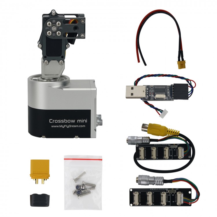
Package Included:
- 1 x Antenna Tracker


")

")

")


