| Quantity | 3+ units | 10+ units | 30+ units | 50+ units | More |
|---|---|---|---|---|---|
| Price /Unit | $41.06 | $40.22 | $38.97 | $37.29 | Contact US |
 AD2S1210 N1 16Bit R/DC High Performance Resolver Transformer Demodulation Module 15.8Vpp Excitation Amplitude
$77.75
AD2S1210 N1 16Bit R/DC High Performance Resolver Transformer Demodulation Module 15.8Vpp Excitation Amplitude
$77.75
 GC-1201S Two-master One-slave Isolated RS485 Hub Repeater Double Electrical Isolation with 12V Power Supply
$36.58
GC-1201S Two-master One-slave Isolated RS485 Hub Repeater Double Electrical Isolation with 12V Power Supply
$36.58
 GC-1201S Two-master One-slave Isolated RS485 Hub Repeater Double Electrical Isolation Support for Modbus Protocol
$33.75
GC-1201S Two-master One-slave Isolated RS485 Hub Repeater Double Electrical Isolation Support for Modbus Protocol
$33.75
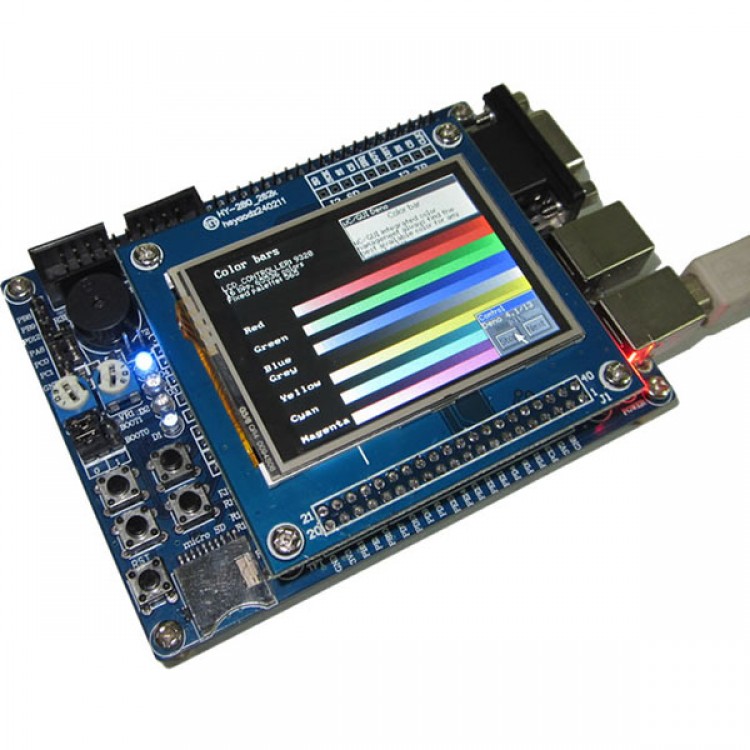
MINI STM32 Dev Board STM32F103VET6 512K FLASH 64K SRAM+2.4 inch LCD Display Screen
Hardware resources:
· CPU: STMicroelectronics (ST) based on ARM Cortex-M3 32-bit processor chips STM32F103VET6 LQFP100 pin chip with 512KB FLASH, 64KB RAM (integrated on-chip 12Bit A / D, D / A, PWM, CAN, USB , SDIO, FSMC and other resources).
32-bit RISC processor performance
32-bit ARM Cortex-M3 structure optimization
72 MHz operating frequency, 1.25 DMIPS / MHz
Hardware division and single-cycle multiply
Quick can be nested interrupts, 6 to 12 clock cycles
with MPU protection setting access rules
· A JTAG debug interface (standard 20-pin).
· A power LED (red), 4 status LED (light-blue).
· An RS232, support 3 line ISP.
· 1 USB2.0 SLAVE mode interface.
· A Micro SD (TF) card socket, interface with SDIO mode.
· A 2.4 inch 26 million color TFT (240X320 (with touch screen) interface, the use of MCU FSMC 16-bit interface mode control. Touch screen with ADS7843 chip with SPI interface.
· An SPI bus control M25P16 (16MB capacity) serial FLASH. Used to store data / code / character and the phase diagram, etc. in SOP8 package can be replaced with a larger capacity FLASH.
· Four function keys.
· An RTC backup battery holder with battery. GPIO port all the leads.
CD-ROM routines include:
1. LCD1602 LCD GPIO mode routines.
2. ADC analog to digital conversion routines.
3. FSMC interface 16 bit mode TFT display routines.
4. LED flashing routines.
5. M25P16 serial FLASH read and write routines.
6. RTC real time clock routine.
7. SDIO interface mode on the SD card file system Tini Fatfs0.07C routines.
8. SDIO interface mode to read and write routines.
9. SysTick test routines.
10. TIM1 of the PWM demonstration routines.
11. UCOSII2.86DEM system routines.
12. PC's USB port to read the SD card (when the reader) routine.
13. USB interface to simulate mouse movement routines.
14 resistive touch screen demonstration routines.
15 asynchronous serial communication routines routines.
16. FSMC 16-bit mode ucos2.86, UCGUI3.90A system routines.
17. USB line programming the MCU driver routines.
Standard shipping list:
- HY-STM32_100P motherboard 1.
- 2,600-color 2.4-inch TFT touch screen 1.
- high-quality USB cable 1.
- RTC clock backup battery 1.
- Fixing studs / screws 4 sets.
- video tutorials and data CD 1.


 +2.8 Inch Color LCD Module Kit")


