| Quantity | 3+ units | 10+ units | 30+ units | 50+ units | More |
|---|---|---|---|---|---|
| Price /Unit | $68.40 | $67.01 | $64.91 | $62.12 | Contact US |
 JHEMCU F405 Wing Flight Control INAV Firmware 5V 8A BEC Built-in Barometer for Fixed Wing FPV Racing Drones
$51.32
JHEMCU F405 Wing Flight Control INAV Firmware 5V 8A BEC Built-in Barometer for Fixed Wing FPV Racing Drones
$51.32
 A6 SE APM Opensource UAV Flight Control with Galvanometer Module and Note3 Ultra GPS for Pixhawk UAV Drones
$234.83
A6 SE APM Opensource UAV Flight Control with Galvanometer Module and Note3 Ultra GPS for Pixhawk UAV Drones
$234.83
 CUAV NEO 4SE High Precision Navigation Opensource GPS Positioning Module for U-blox M10 Satellite Receiving
$73.67
CUAV NEO 4SE High Precision Navigation Opensource GPS Positioning Module for U-blox M10 Satellite Receiving
$73.67
OpenPiolot CC3D Revolution Flight Controller + OPLINK MINI & 2-6S Distribution Board for FPV Photography
CC3D Revolution Description:
- The OpenPilot Revolution board, also called 'Revo', is a new breed of Autopilot using the STM32F4 series, 210MIPS ARM Micro-controller. This is important, as it contains a hardware floating point unit (FPU), which is a huge advancement for hobby-class autopilots. Of course, OpenPilot has been 32bit since day one, and the FPU is another step up the performance ladder. The FPU allows precise, low-latency processing of real-life measurements using advanced attitude estimation algorithms.
- The Revolution is a flight control computer with autopilot, intended for multirotors, helicopters and fixed wings. It is a full 10DOF with gyroscope, accelerometer, magnetometer and pressure sensors.
Technical description
CPU
- CPU is the STM32F405RGT6 chip, with ARM Cortex-M4 core at 210MIPS, FPU, and saturation arithmetics DSP functions.
- The chip features a range of built-in hardware modules that can bo programmed once and function independently, requiring little to no CPU overhead. These include 14x multichanel timers, 3x synchronous-sampling ADC serving up to 24 channels, 2x DAC, matrix memory controller with 16-stream DMA, and other. Communication modules include USB2.0, 3x I2C, 3x SPI, 4x USART, 2x CAN and SIDO. All these modules can be configured for accessing the chip pins using a flexible switch matrix, or disabled to save power.
- It even contains a real time hardware calendar if you want a wake up flight.
- The software and settings are loaded through USB connector and no-hassle update function in the GCS (Ground Control Station).
Modem
- The board features a built-in 433MHz OPLink Modem.
Dimensions
- OpenPilot products use the standard OpenPilot footprint, and hence has the same dimensions and mounting holes as the OpenPilot CC. CC3D, Revo, GPS, OSD and PipX boards.
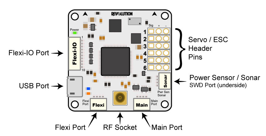
Ports:
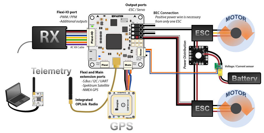
- Servo 1-6: These are the PWM outputs that go to servos or electronic speed controllers (ESCs). Power for the flight controller is typically supplied through these headers from only one of the ESCs, but in most cases, all the servo wires can be left connected. Cutting the pin from servo wires is highly discouraged. If you feel you must disconnect three of the hot wires, use some shrink tube or electrical tape to insulate the removed pin (you may need that positive voltage at a later date!). The positive (Vcc) and negative (Gnd) pins are indicated on this diagram and the board. In rare cases, you may need to also disconnect the ground pin if your ESCs are creating ground loop problems (indicated by a general weirdness in setup). (see the CopterControl - CC3D -Atom Hardware Setup page, Power section, for instructions on how to remove and insulate the extra pins)
Servo output pin layout is:
- Outside --> ground
- Middle --> 5V - 8.4V
- Inside --> signal
Flexi-IO Port: JST-SH 10-pin. The receiver port can act as an input or output port depending on the configuration which is set in the Hardware Settings. Configuring the receiver port as an output port allows the user to assign more output channels then the 6 standard servo outputs.
PWM -vs- PPM Recievers
- Please be aware that not all receivers can be configured to use a PPM output. It is the user's responsibility to research this feature in regards to the desired receiver they wish to use for PPM and ensure it can be used as such. Many hours of frustration can occur while trying to troubleshoot why you can't get your radio to connect to the board with PPM if using a receiver than isn't designed with that feature! Simply make sure the receiver can do it before trying to set it up that way.
MainPort: JST-SH 4-pin. This is a serial USART whose baud rate can be adjusted through the GCS. Optionally, Futaba S.Bus receiver, Spektrum/JR satellite receiver or GPS can be mapped to the MainPort. Default configuration is Telemetry for connecting an RF modem.
FlexiPort: JST-SH 4-pin. The function of this port also depends on the configuration and can be configured for I2C or Serial. The default configuration doesn't use this port, but it can be used for Telemetry, GPS, Spektrum satellite receivers (all working), and other I2C peripherals (under development).
RF Socket: Antenna connection socket for on-board OPLink modem.
Pwr Sen/Sonar Port: JST-SH 4-pin. This port can be configured to accommodate an Autopilot current sensor and a low cost Sonar sensor such as the HC-SR04. It can also be used as a general purpose input/output port or as a one or two channel analog input port.
Please note that the output rate on the output channels from the Flexi-IO Port cannot be set individually. If servos are connected to this outputs, you must ensure that they can work with the defined output rate for the bound channel. E.g. if you choose a high output rate to support an octocopter configuration, the update rate from the output channels from the ReceiverPort are bound to the update rate from channels 5 & 6. In this case, you cannot connect analog servo's to these outputs since an analog servo only supports an output rate of 50Hz..
Sensor suite
3 Axis Gyro
3 Axis Accelerometer
3 Axis Magnetometer
Barometric pressure sensor
Gyro/Accelerometer OPLM Transceiver Description:
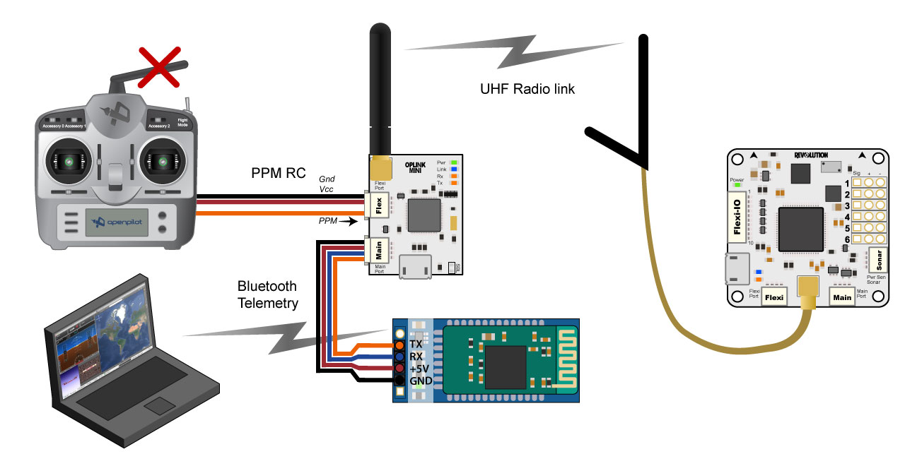
- The OPLink is a radio transceiver backed by an ARM32 powered digital packet processor specifically designed for the OpenPilot project, it was originally developed under the codename: PipXtreme and there are many artifacts that still reflect this. It is a two-way radio system allowing real time telemetry information for the Ground Control Station, Wireless Configuration and even radio control from your transmitter over a single communications link.
- You will need two OPLink radios to establish a connection between the vehicle and ground station. Note that the Revolution board has an OPLink built into the flight controller. The same firmware version must be running in Revo and OPLM devices (i.e. if you upgrade one board, you will need to upgrade all others that are 'bound' together).
- The OPLM units operate at 433Mhz. This means that there will be a frequency conflict if you operate the vehicle using a UHF 433Mhz system. In basic terms, this conflict will lead to a loss of vehicle control and / or a crash. Use transmitters in other parts of the spectrum (i.e. 2.4G, 27Mhz, 36Mhz) for vehicle control if you intend to enable the OPLink on your Revo for transmission of telemetry data. If you wish to use a 433Mhz transmitter for vehicle control, then use an OPLM which will by default, enable the transmission of telemetry.
- Check local laws and regulations regarding radio licensing, see our Radio Licensing article for more information.
- The device that is intended to undertake the most of the transmissions should be allocated as the Co-ordinator. If you wish to use the OPLM for vehicle control, then the Co-ordinator should be the OPLM device in your transmitter module at the ground station. In this case, the Revo or another OPLink will be acting as a slave receiver but will also transmit telemetry information to your ground station which is comprised of another OPLM connected to a computer that is running the OP GCS Flight Data page. Alternatively, if you wish to simply receive telemetry data at the ground station, then the Revo should be configured as the Co-ordinator. Configuration instructions are provided below and linked-to pages.
First time use with OPLM
- When you first try to use your OPLM with the GCS, it will not be automatically picked up by the GCS. You first need to go into the 'Firmware' tab and click 'Upgrade & Erase' while the OPLink is disconnected. Then plug in OPLink when the upgrade process asks for it. Once this has been done, your OPLM board will show up at the bottom of your GCS as a connected device. The configuration page icon at the bottom of the page icon list may be hidden without scrolling down, depending on the size of your computer screen.
OPLink Mini
- 100mW Standalone Radio Modem
- 3 IO Ports: Micro-B USB, Mainport & Flexiport
- MMCX Antenna Connector.
- Weight: 4g
- Dimensions: 20mm x 29mm
- Input Voltage: +5v
2-6S Distribution Board Description:
- CC3D revolution distribution board is wtih two channels of BEC output, 2-6S output, 5V output 3.A 12V output 3A
- If you need 12V stable output, the min input is 4S.
- The holes pitch is exactly the same with CC3D revolution flight control board
- Adopting copper shielding cover, high quality and performance, low price
- Adopting high standard industrial TI chip, and optimize the PCB board, after the repeated testing, it turns out to be a satisfactory product.
- Thicken copper cover, great stability, with shielding cover
- Weight: 8g
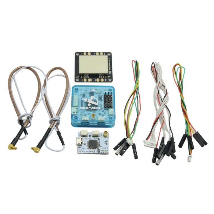
Package includes:
- OPLM CC3D Revolution flight controller x 1
- OPLINK MINI OPLM Radio Transceiver x 1
- 2-6S Distribution Board x 1