| Quantity | 3+ units | 10+ units | 30+ units | 50+ units | More |
|---|---|---|---|---|---|
| Price /Unit | $3.24 | $3.18 | $3.08 | $2.95 | Contact US |
 LC29HBS Dual Band Multi-constellation Base Station GNSS Module + Antenna with RTK Function GPS/BDS/Galileo/QZSS/GLONASS
$45.10
LC29HBS Dual Band Multi-constellation Base Station GNSS Module + Antenna with RTK Function GPS/BDS/Galileo/QZSS/GLONASS
$45.10
 LC29HBS Dual Band Multi-constellation Base Station GNSS Module with RTK Function GPS/BDS/Galileo/QZSS/GLONASS
$33.44
LC29HBS Dual Band Multi-constellation Base Station GNSS Module with RTK Function GPS/BDS/Galileo/QZSS/GLONASS
$33.44
 LC29HDA Dual Band Multi-constellation Mobile Station GNSS Module + Antenna with RTK Function GPS/BDS/Galileo/QZSS/GLONASS
$49.96
LC29HDA Dual Band Multi-constellation Mobile Station GNSS Module + Antenna with RTK Function GPS/BDS/Galileo/QZSS/GLONASS
$49.96
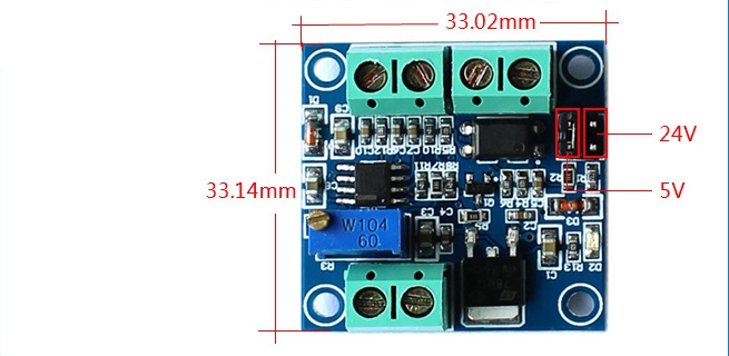
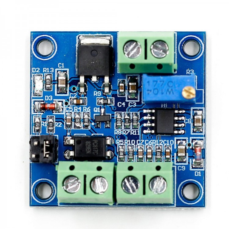
PWM To Voltage Converter Module 0%-100% To 0-10V For PLC MCU Digital to Analog Signal PWM Adjustable
Description:
The PWM transfer voltage module LC-LM358-PWM2V converts the PWM digital signals into 0 to 10V analog signals.
It can be used as signal interface switching for PLC or other industrial control boards. The output voltage is regulated by adjusting the duty ratio of the PWM. The modules are small in size and easy to use in different places.
Features:
- MCU embedded technology
- Easy to operate, fine tuned by potentiometer
- Select the PWM signal input level range through short-circuit
- The module is smaller, easy to carry and use
Parameters:
- Work Voltage: DC 12V-30V (> 100MA)
- PWM Receiver Frequency: 1KHZ-3KHZ
- PWM signal input level range:
* The peak of 4.5V to 10V level. The short cap install in 5V. This level is used for normal controller or 5V MCU;
* The peak of 12V to 24V level, so inserted in 24V. The short cap install in 24V. This level is used for normal PLC controller.
- Conversion range: 0%-100% PWM to 0-10V
- Allowable error: 5%
Package Included:
- 1 x Module
Wiring Instruction:
- VCC: To Working Power Supply
- GND: To Power Supply Ground
- F: To Input Frequency Pulse Signal
- GND: To Input Ground
- VOUT: To Output Related Voltage
- GND: To Output Ground
Attention:
- The module shares ground.
- Connect working voltage to VCC and GND. Reverse connection is not allowed to avoid damage to the board and device.
- Connect frequency pulse signal to F. And there will be related voltage output in VOUT terminal
- Relationship between input and output: 100Hz = 1V. 1KHz = 10V.
- The accuracy of this module is 1%. It is not for uses needing higher accuracy.
- When there is bias of related relationship, use on-board potentiometer to calibrate.
Hardware Interfaces:
- VCC: Working Power Supply DC 12V-30V
- GND: Working Power Supply Ground
- PWM: Input Signal PWM +
- GND: Input Signal -
- VOUT: Output Voltage 0-10V
- GND: Output Voltage Ground
Operation Instructions:
After power on, there is no input signal, so the output is 0V. When there is input, there will be output. The first time when it is power-on, it is best to do a calibration debugging: Input a 50% duty cycle signal to PWM/GND and to the jumper related to amplitude.
Frequency is 1KHZ-3KHZ, measured VOUT and GND with a multimeter and it will display about 5V. Adjust on-board potentiometer to make sure display 5.00V on the multimeter. In this way, the correspondence between your pulse signal and this module is calibrated.
When frequency changes, the correspondences may be offset and need to be re calibrated. Output voltage can be adjusted by adjusting duty cycle. Accuracy can be controlled by adjusting the potentiometer.