| Quantity | 3+ units | 10+ units | 30+ units | 50+ units | More |
|---|---|---|---|---|---|
| Price /Unit | $148.23 | $145.20 | $140.66 | $134.61 | Contact US |
 Silvery RC Pedal Game Throttle Hydraulic Clutch Racing Simulator Pedal Remastered Version Support for SIMPRO Software Adjustment
$339.98
Silvery RC Pedal Game Throttle Hydraulic Clutch Racing Simulator Pedal Remastered Version Support for SIMPRO Software Adjustment
$339.98
 Second Generation RC Car Engine Sound Simulator Throttle Linkage Sound Groups Speaker for RC Vehicle
$28.46
Second Generation RC Car Engine Sound Simulator Throttle Linkage Sound Groups Speaker for RC Vehicle
$28.46
 12 LED Lighting System Kit Smart Simulation RC Car Lights for Tamiya RC Car Parts 1/10 Drift Vehicle
$10.99
12 LED Lighting System Kit Smart Simulation RC Car Lights for Tamiya RC Car Parts 1/10 Drift Vehicle
$10.99
RoboModule DC Servo Motor Driver RMDS-405 Standard Version One-Ended Encoder Interface For AGV
Description (Standard Version):
Its internal current sensor is a 30A Hall current sensor. It can feed back current normally and work in current closed-loop related mode, providing over-current protection. The disadvantage is that the 30A Hall current sensor is the current bottleneck of the entire drive. Under abnormal and over-rated conditions, the current sensor may fuse and burn.
Features:
- 10 to 58V, 30A (12V 16V 24V 36V 48V)
- 300g body heat dissipation
- CAN bus
- RS485 bus
- Pulse direction PWM
- Analog input PPM
- RS232 communication connection to host computer
- One key to rescue firmware
- Reserved isolated output
- With buzzer prompt
- High current connector adopts model airplane XT60 connector, which can withstand 45A current for a long time
Download Materials Here:
http://www.robomodule.net/download.html
Improvements of RMDS-405 (Compared with RMDS-402):
1. Reinforce the processing of RS485 interface
2. Re-enhance the processing of RS232 interface
3. Current sampling sensor with better accuracy
4. Improve encoder's interface and enhance anti-interference ability. Please pay attention to the encoder interface: If RMDS-405 needs to use an encoder with open collector output, the CHA and CHB of the encoder need to be pulled up to +5V externally, and the resistance value is 2k~15k. To avoid unnecessary troubles, please try to use push-pull output or voltage output encoders, and try to avoid open-collector output encoders
Three Generations of Products Remain Fully Compatible:
1. 405/402/401 share the same program and are fully compatible.
2. The external interface definitions of 405/402/401 are exactly the same and fully compatible.
3. From the shell, everything is unchanged, only the model names such as 401/402/405 have changed.
XT60 Plug Soldering:
1. XT60 plug is best to use 12AWG or 14AWG high temperature resistant silicone wire. If you use ordinary wires that are not resistant to high temperatures, high current may cause the wires to heat up, melt and burn.
2. For soldering XT60 plugs, use lead-free tin wire is the best. The recommended solder wire composition is Sn99.3 Cu0.7. If you use lead tin wire, the solder joints may become black and loose after long-term use and cause gaps, which will eventually lead to soldering. The point completely fails.
3. After welding the plug, please put on the heat shrinkable tube. The finished welding product is shown in the figure below
Precautions for plugging and unplugging the XT60 interface:
After the XT60 interface is plugged and unplugged many times, the metal petals of the XT60 may shrink and shrink, and the specific performance is that the plugging and unplugging becomes easier and easier. This may result in blackening of the contacts after high current.
The solution is as follows:
1. Minimize the number of times of plugging and unplugging the XT60 plug.
2. If you find that the petals of XT60 have shrunk after multiple insertions and unplugging, use a Phillips screwdriver to insert and pry the petals larger.
Special note about 485 interface:
- This 485 interface does not support for Modbus protocol, nor can it be used together with for Modbus protocol devices on the same 485 bus.
- This 485 interface can only be used with RMDS series drives. A 485 bus can connect up to 15 drives at the same time.
- Under normal circumstances, if the master has a CAN bus interface. Compared with CAN bus, it is not recommended to use 485 communication.
Product Characteristics:
1. Fully automatic SMT soldering, high temperature lead-free process, to prevent displacement of components due to overheated solder melting
2. The XT60 connector is used to connect the power supply and the motor, which can withstand a long-term current of 30A
3. Use a base with a wrinkled heat sink, and the MOSFET and the heat sink are closely attached with a thermally conductive silicone sheet
4. For high-current wiring, use tin wire to thicken, widen and heighten
5. Adopting the low ESR capacitors of Japan Chemical Industry, the heat generated by the capacitor is greatly reduced
6. Withstand voltage design of ICs and devices related to the input power supply is selected according to the 100V standard, leaving a margin of 1.7 times, which can avoid damage to the motor's power generation surge to a certain extent
7. The weight of the drive is about 300g, including the shell radiator and all plugs
Application Scenarios:
1. Food delivery robot
2. Welcome Robot
3. Bank Robot/Hospital Robot
4. Other service robots, etc.
5. AGV single weight truck
6. Unmanned ship propeller
7. Small armored chassis/small armored tank chassis
8. Other mobile robot chassis, etc.
9. Small heavy objects lifting and hoisting applications, etc.
Interface Definition:
Power Supply:
PW+: Power input +/VCC, 10-58V
PW-: Power input -/GND
Motor:
MT1: Motor connection port, no need to distinguish between positive and negative
MT2: Motor connection port, no need to distinguish between positive and negative
Encoder:
GND: GND of encoder
CHZ: Z-phase or I-phase of the encoder, may not be connected
CHA: Phase A signal of the encoder
+5V: 5V power output port for powering the encoder
CHB: Phase B signal of the encoder
Digital Communications:
485A: Port A of 485 bus
485B: Port B of 485 bus
GND: 485 bus or CAN bus reference GND
CANH: H port of CAN bus
CANL: L port of CAN bus
232R: RXD port for RS232 communication
GND: Reference GND for RS232 communication
232T: TXD port for RS232 communication
Multifunctional Input:
CTL1-, CTL1+: 5V direction input ports, which are optocoupler isolated differential ports, which require at least 11mA current to drive, and can also be connected to limit switches
CTL2-, CTL2+: 5V pulse/PWM/PPM input ports, which are optocoupler-isolated differential ports that require at least 11mA current to drive, and can also be connected to limit switches
Isolated Output:
OUT2: Isolated open collector output 2 of the output port
OUT1: Isolated open collector output 1 of the output port
OCOM: Common cathode of isolated output port
Reserved Port:
3V3: 3.3V reserved port, if you need to supply external power, the current draw should not exceed 50mA
GND: reserved GND port for use with the port for erasing firmware
SOS: Erase the firmware port, if needed, short-circuit it to GND
Attention:
1. Download information/instructions: www.robomodule.net enter the download area, please read the instructions carefully before operation.
2. Please connect it to a power supply correctly. Reverse connection is forbidden.
3. When your motor is working, it is forbidden to cut off the power directly! Otherwise, a very high power generation voltage may be generated, which may burn the drive.
4. 232T, 232R, CANH, CANL, 485A, 485B, CTL1, CTL2, ASIN, DSIN, CHA, CHB and other signal interfaces.
a. It is forbidden to go on wiring, change the wiring, and plug or unplug when the drive is energized.
b. It is forbidden to directly touch the conductive frame.
c. Prohibit direct contact with objects that may be charged with static electricity.
d. It is forbidden to directly touch the high-voltage power supply (12V/24V/36V/48V and motor wires, etc.).
Otherwise, there is a high probability that the driver's interface will be permanently damaged. Please confirm that the wiring is correct before turning on the power.
5. When in use, it is best to use battery power directly (without any conversion). Battery is not included.
Precautions:
- Power supply is forbidden to be connected reversely.
- It is forbidden to plug and unplug the terminal under the electrified state.
- No live wiring.
- When using a motor with a power greater than 100watt or a diameter greater than 40mm, be sure to use a battery to power it directly. Because a motor with a large moment of inertia will generate a surge voltage much larger than the power supply voltage at the moment the speed decreases sharply or runs CCW. This surge voltage can be completely absorbed by the battery, but other types of power supplies cannot. It will cause damage to the drive or power supply. If you use the current mode, there is no need to consider the above situation. Battery is not included.
RMDS-405 Parameters:
Appearance parameters of the whole machine:
- Product weight: 296g
- Product size (size without plug): 118mm*76mm*33mm
- Shell material: aluminum (black anodized surface treatment)
Temperature range:
- Storage temperature: 10℃ to 35℃
- Working temperature: industrial grade -40℃ to 85℃
PCB/PCBA parameters:
- PCB size: 101.3mm*69.4mm*1.6mm
- Number of layers: 4
- PCB thickness: 1.6mm
- Surface treatment: lead-free tin spray or immersion gold
- Welding method: automatic vision correction SMT
- Solder paste material: high-temperature environmentally friendly lead-free solder paste, resolutely resist low-temperature lead-containing solder paste
Voltage, current and power:
- Input voltage range (VCC): 10V~58V
- Typical supply voltage: 12V, 16V, 24V, 36V, 48V
- Continuous current support: 30A
- Maximum short-time current: 60A
- Maximum motor power supported at 12V: 360w
- Maximum motor power supported at 16V: 480w
- Maximum motor power supported at 24V: 720w
- Maximum motor power supported at 36V: 1080w
- Maximum motor power supported at 48V: 1440w
Static power consumption (only connected to power supply):
- Standby current when 12.0V power supply: 35mA
- Standby current when 16.0V power supply: 28mA
- Standby current when 24.0V power supply: 21mA
- Standby current at 30.0V power supply: 19mA
- Standby current at 36.0V power supply: 16mA
- Standby current at 48.0V power supply: 11mA
Operating mode:
- Open loop mode: This mode is used to control the motor in an open loop. In general, if the motor is no-load or micro-load, the greater the PWM value, the faster the motor speed. The smaller the PWM value, the slower the motor speed. If the PWM value is equal to 0, the motor stops rotating, and the motor is in a damping locked state at this time. When a fixed PWM is given, such as PWM=1000, the larger the motor load, the slower the speed, and the smaller the motor load, the faster the speed. This mode can be used to test whether the motor encoder works normally.
- Current mode: This mode does not call the encoder parameters, so there is no need to connect the encoder. 1. When used to control the current in the coil, when a certain current value is given, such as 1A, the current in the coil will be kept at the current value of 1A. This can be used to control the electromagnet to obtain the effect of adjustable suction, which can be used for magnetic levitation. 2. When used in a motor that can rotate freely, when the force generated by a given current value is greater than the static friction force of the motor, the motor obtains acceleration and gradually accelerates to the maximum speed with this acceleration value. 3. When used to control a motor that rotates within the limit, when the motor is restricted and stops locked, the locked-rotor current will remain at the set current value, as long as the current value does not exceed the rated current of the motor, the locked-rotor will also be blocked for a long time. Will not burn the motor.
- Speed mode: This mode needs to be connected to an encoder, and it needs to be in open loop mode 2. In CW, the encoder feeds back positive speed, and in CCW, the encoder feeds back negative speed. This mode is suitable for closed-loop control of the motor speed. When a fixed speed value is set, such as 1000RPM, the motor will maintain this speed value. This speed will remain the same regardless of whether the load becomes larger or smaller. When the speed is 0, the motor stops rotating and locks at the current position. When used for the chassis motor control of a car/robot/mobile platform, it is different from the open-loop mode. This mode can make the motor speed as low as 1RPM, while the open-loop mode is difficult to achieve such a low speed. In the open-loop mode, the speed will slow down when encountering an uphill slope, and the speed will become faster when encountering a downhill slope. In the speed mode, the speed will not change because of uphill or downhill.
- Position mode: In this mode, an encoder needs to be connected, and it must be ensured that in open loop mode 2, the encoder feedbacks positive speed in CW, and in CCW, the encoder feedbacks negative speed. This mode is provided for motors of low-resolution encoders using position closed loop to control the motor to rotate from position A to position B, and lock in position B but do not control the speed during rotation. Therefore, the maximum speed of movement from point A to point B can only be restricted by adjusting and limiting the PWM duty cycle. Therefore, it is not possible to control the motor to work at a very low speed, such as 1RPM. The encoder accuracy is greater than 100 servo motors, it is recommended to use the speed position mode to obtain better control effect.
- Speed position mode: In this mode, an encoder needs to be connected, and it must be ensured that in open loop mode 2, the encoder feedbacks positive speed in CW, and the encoder feedbacks negative speed in CCW. This mode is provided for motors with high resolution encoders to use position closed loop, such as encoders with 500 lines. It can control the movement of the motor from point A to point B, and control the speed of its rotation process. The position control accuracy of this mode is the highest among all position modes.
- Current speed mode: In this mode, an encoder needs to be connected, and it must be ensured that in open loop mode 2, the encoder feedbacks positive speed in CW, and the encoder feedbacks negative speed in CCW. When used on a light-loaded motor, change from A speed to B speed, and the motor will change from A speed to B speed with a constant acceleration. When the motor is blocked by an external force, the locked-rotor current will maintain the set current value. When the external force is removed, the motor continues to recover to the last set speed with a constant acceleration. The magnitude of this acceleration is positively related to the current setting value.
- Current position mode: In this mode, an encoder needs to be connected, and it must be ensured that in the open loop mode 2, the encoder feedbacks positive speed in CW, and the encoder feedbacks negative speed in CCW. Use this mode to set the motor to move from point A to point B. The motor will move directly from point A to point B without controlling the speed. When the movement process is blocked by external force, the motor will maintain this set current. When the external force is removed, the motor will continue to resume movement until it reaches point B.
- Current speed position mode: In this mode, an encoder needs to be connected, and it must be ensured that in open loop mode 2, the encoder feedbacks positive speed in CW, and the encoder feedbacks negative speed in CCW. Use this mode to set the motor to move from point A to point B. During the movement, the set speed will be maintained. The acceleration during the acceleration process is positively correlated with the set current value, and it will stop after moving to point B. When the movement process is blocked by external force, the motor will maintain this set current. When the external force is removed, the motor will continue to resume movement until it reaches point B.
About current:
- Current unit: mA
- Controllable minimum current value: 1mA
- The current range that can be set: -32768mA to +32767mA (Note: Setting beyond the maximum continuous current range is risky)
About speed:
- Speed unit: RPM
- Controllable minimum speed value: 1RPM
- Settable speed range: -32768RPM to +32768RPM (Note: the setting beyond the motor rated speed range is meaningless)
About location:
- Location unit: qc
- Controllable minimum position value: 1qc
- Settable position range: -2147483648qc to +2147483647qc
The data about the speed current position is returned:
- Return method: periodically return or not return
- Return channel: CAN bus/RS232
- Return cycle: can be set
- Return period range: set 0ms as no return, and the set period range is 1ms~255ms
RS232 interface:
- 232R port withstand voltage range: -12V to +12V (built-in ±12V ESD)
- 232T port withstand voltage range: -12V to +12V (built-in ±12V ESD)
- Factory default RS232 baud rate: 115200
- Fixed configuration of serial port: 8 data bits/1 stop bit/no parity/no flow control
- Data packet size: each data packet is fixed at 10 bytes
- Whether the baud rate is adjustable: adjustable
- Baud rate optional range: 921600, 460800, 230400, 115200, 57600, 38400, 19200, 14400, 9600, 4800
- The specified baud rate when upgrading the firmware: 115200
CAN interface:
- CANH/CANL interface withstand voltage range: -24V to +24V (built-in ±24V ESD)
- Factory default CAN baud rate: 1Mbps
- Whether CAN baud rate is adjustable: adjustable
- Baud rate optional range: 1M, 800k, 500k, 250k, 125k, 100k, 50k, 20k, 10k, 5k
- CAN communication fixed configuration: standard frame, data frame, frame length 8 (cannot be modified)
- Whether built-in 120R terminal resistance: the internal default does not weld 120R resistance
- Whether to support broadcasting: support group broadcasting
- Group numbering situation: 8 groups, 15 members in each group
- Support the number of drives attached at the same time: 120
- Factory default node number: 0 group 1 number
485 interface:
- 485A/485B interface withstand voltage range: -7V to +12V (built-in -7/+12ESD)
- Whether 485 baud rate is adjustable: adjustable
- Baud rate optional range: 921600, 460800, 230400, 115200, 57600, 38400, 19200, 14400, 9600, 4800
- 485 communication fixed configuration: 8 data bits/1 stop bit/no parity/no flow control
- Whether built-in 120R terminal resistance: the internal default does not weld 120R resistance
- Whether to support broadcasting: support broadcasting
- Numbering situation: No. 1~15
- Support the number of drives attached at the same time: 15
- Factory default node number: No. 1
RMDS-405 CTL1+/CTL1-, CTL2+/CTL2- hardware description:
- Isolation method: optocoupler isolation
- Optocoupler type: high-speed optocoupler
- Optocoupler model: TLP2362
- Optocoupler forward voltage drop: 1.55V
- The maximum current allowed by the optocoupler: 20mA
- Lowest lighting current of optocoupler: 5mA
- Built-in current limiting resistor: 1K in parallel with optocoupler, and then in series with 300R
- After considering the built-in resistance, the lowest lighting voltage: (1.55/1000+0.005)*300 +1.55=3.515V
- When 5.0V is lit, the overall input current: (5.0-1.55)/300=11.5mA
- When 5.0V is lit, the current flowing through the optocoupler: 11.5-(1.55/1)=9.95mA
- Reverse power supply withstand voltage: -8V
- Maximum input voltage value of forward power supply: (1.55/1000+0.02)*300+1.55=8.015V
RMDS-405 CTL1/CTL2 limit feedback:
- Limit switch input port 1: CTL1+, CTL1-
- Limit switch No. 2 input port: CTL2+, CTL2-
- Communication methods that can use limit feedback: RS232 communication, CAN communication
- Port status feedback mode: regular return or no return
- Port status feedback cycle: configurable, range 0ms~255ms (configure 0ms to not return)
- The state of the optocoupler corresponds to the level: the optocoupler is on = high level, and the optocoupler is off = low level
- Default port status: optocoupler off = low level
- Limit switch and CTL1 connection: CTL1- connect to GND, CTL1+ connect to one end of the limit switch, and the other end of the limit switch to 5V
- Limit switch and CTL2 connection: CTL2- connect to GND, CTL2+ connect to one end of the limit switch, and the other end of the limit switch to 5V
Pulse direction input of RMDS-405 CTL1/CTL2:
- Pulse input port: CTL2+, CTL2-
- Direction input port: CTL1+, CTL1-
- Controllable motion modes: position mode/speed position mode
- Recommended sport mode: speed position mode
- Whether the electronic gear ratio is adjustable: adjustable
- Supported frequency range: not more than 180kHz
- The connection method of the pulse direction interface and PLC (24V): CTL2- connects to the pulse port of PLC, CTL2+ connects to one end of a 1.6K resistor, and the other end of the 1.6K resistor connects to the 24V power port of PLC. CTL1- is connected to the direction port of the PLC, CTL1+ is connected to one end of the 1.6K resistor, and the other end of the 1.6K resistor is connected to the 24V power port of the PLC.
- The connection method of pulse direction interface and PLC (5V): CTL2+, CTL1+ connect to 5V of PLC, CTL2- connect to the pulse output port of PLC, CTL1- connect to the direction output port of PLC.
- The connection method of the pulse direction interface and the MCU: CTL2+, CTL1+ are connected to the 5V of the external MCU, CTL2- connected to the pulse output port of the MCU, CTL1- connected to the direction output port of the MCU. (No matter 3.3V or 5VMCU can be connected by this)
PPM input of RMDS-405 CTL1/CTL2:
- PPM input port: CTL2+, CTL2-
- Control rotation direction input port (not necessary): CTL1+, CTL1-
- Controllable motion modes: open loop mode/speed mode/current mode/current speed mode
- Supported frequency range: 50Hz~400Hz
- Recommended frequency: 400Hz
- Effective high level range: 1000us~2000us
- Whether the electronic gear ratio is adjustable: adjustable
- Connection between PPM input interface and steering gear tester (1500us split forward and reverse mode): CTL2+ is connected to 5V, CTL2- is connected to the collector of NPN transistor, the emitter of NPN transistor is connected to GND, and the base of NPN transistor is connected to the steering gear test The signal output port of the device.
- PPM input interface and MCU connection (1500us split forward and reverse mode): CTL2+ connects to the 5V of the external MCU, CTL2- connects to the PPM output port of the MCU. CTL1+, CTL1- float. (Note that this connection requires the output waveform to be inverted)
- PPM input interface and MCU connection (use additional ports to control forward and reverse): CTL2+, CTL1+ connect to the 5V of the external MCU, CTL2- connect to the PPM output port of the MCU. CTL1-Connect to the direction output port of MCU. (Note that this connection requires the output waveform to be inverted)
- PPM input interface and PLC (5V) connection method (1500us split forward and reverse mode): CTL2+ is connected to 5V of PLC, CTL2- is connected to PPM output port of PLC, CTL1+, CTL1- are suspended. (Note that this connection requires the output waveform to be inverted)
- PPM input interface and PLC (5V) connection method (use an additional 10 to control forward and reverse rotation): CTL2+, CTL1+ connect to 5V of PLC, CTL2- connect to PPM output port of PLC, CTL1- connect to direction output port of PLC. (Note that this connection requires the output waveform to be inverted)
- PPM input interface and PLC (24V) connection method (1500us split forward and reverse mode): CTL2- connects to the PPM output port of the PLC, CTL2+ connects to one end of the 1.6K resistor, and the other end of the 1.6K resistor connects to the 24V power port of the PLC. CTL1+, CTL1- float. (Note that this connection requires the output waveform to be inverted)
- PPM input interface and PLC (24V) connection method (use additional ports to control forward and reverse rotation): CTL2- connects to the PPM output port of the PLC, CTL2+ connects to one end of the 1.6K resistor, and the other end of the 1.6K resistor connects to the 24V power port of the PLC . CTL1- is connected to the direction port of the PLC, CTL2+ is connected to one end of the 1.6K resistor, and the other end of the 1.6K resistor is connected to the 24V power port of the PLC. (Note that this connection requires the output waveform to be inverted)
PWM duty cycle input of RMDS-405 CTL1/CTL2:
- PWM duty cycle input port: CTL2+, CTL2-
- Control rotation direction input port (not necessary): CTL1+, CTL1-
- Controllable motion modes: open loop mode/speed mode/current mode/current speed mode
- Supported frequency range: 100Hz-1kHz
- Recommended frequency: 1kHz
- Effective duty cycle range: 2%-98%
- Whether the electronic gear ratio is adjustable: adjustable
- The connection of the PWM input interface and the MCU (50% duty cycle divided forward and reverse mode): CTL2+ is connected to the 5V of the external single-chip microcomputer, and CTL2- is connected to the PWM output port of the single-chip microcomputer. CTL1+, CTL1- floating (note that this connection requires the output waveform to be inverted)
- The connection of the PWM input interface and the MCU (use additional IO to control the forward and reverse rotation): CTL2+, CTL1+ connect to the 5V of the external MCU, and CTL2- connect to the PWM output port of the MCU. CTL1-Connect to the direction output port of MCU. (Note that this connection requires the output waveform to be inverted)
- The connection between the PWM input interface and the PLC (5V) (50% duty cycle split forward and reverse mode): CTL2+ connects to the 5V of the PLC, CTL2- connects to the PWM output port of the PLC, CTL1+, CTL1- float (note, this connection (Requires output waveform inversion)
- PWM input interface and PLC (5V) connection method (use additional IO to control forward and reverse rotation): CTL2+, CTL1+ connect to PLC's 5V, CTL2- connect to PLC's PWM output port, CTL1- connect to PLC's direction output port. (Note that this connection requires the output waveform to be inverted)
- The connection method of PWM input interface and PLC (24V) (50% duty cycle division forward and reverse mode): CTL2- connects to the PWM output port of PLC, CTL2+ connects to one end of the 1.6K resistor, and the other end of the 1.6K resistor to the PLC 24V power port. CTL1+, CTL1- float. (Note that this connection requires the output waveform to be inverted)
- The connection between the PWM input interface and the PLC (24V) (use additional IO to control the forward and reverse rotation): CTL2- is connected to the PWM output port of the PLC, CTL2+ is connected to one end of the 1.6K resistor and the other end of the 1.6K resistor is connected to the 24V power port of the PLC . CTL1- is connected to the direction port of the PLC, CTL1+ is connected to one end of the 1.6K resistor, and the other end of the 1.6K resistor is connected to the 24V power port of the PLC. (Note that this connection requires the output waveform to be inverted)
ASIN/DSIN 0-5V/0-10V input:
- Analog input port: ASIN
- Control the rotation direction input port (not necessary): DSIN
- Controllable motion modes: open loop mode/speed mode/current mode
- ASIN port withstand voltage range: 0V~+12V
- DSIN port withstand voltage range: 0V~+5.5V
- Whether the electronic gear ratio is adjustable: adjustable
- Connection of analog input and potentiometer (5V or 2.5V divided forward and reverse mode): The first and third pins of the potentiometer are respectively connected to the GND and +5V of the driver, and the middle pin of the potentiometer is connected to the ASIN of the driver.
- Connection of analog input and single-chip microcomputer (5V or 2.5V split positive and negative mode): The ASIN port of the driver is connected to the analog output port of the single-chip microcomputer, and the GND of the driver is connected to the GND of the single-chip microcomputer. Among them, GND is indispensable, even if the power supply has a common ground, it must be connected to one more.
- Connection of analog input and single-chip microcomputer (using additional IO to control CW CCW): The ASIN port of the driver is connected to the analog output port of the single-chip microcomputer, the DS IN port of the driver is connected to the ordinary port of the single-chip microcomputer, and the GND of the driver is connected to the GND of the single-chip microcomputer. Among them, GND is indispensable, even if the power supply has a common ground, it must be connected to one more.
Encoder:
- Support encoder form: AB or ABZ encoder
- Support encoder level type: voltage output/push-pull output/open collector output/RS422 differential output or differential or long-line output
- Whether to support differential encoder: Yes, it can be connected in a single-ended way
- Encoder CHA/CHB withstand voltage range: 0V to +5.5V
- Encoder power output supply voltage: +5V
- Encoder power output supply current: Imax=100mA
- Encoder frequency multiplication processing: 4 times frequency (not adjustable)
MT1/MT2 motor output port:
- Control the motor's PWM frequency: 14.4KHZ or 28.8KHZ
- PWM resolution of the control motor: 5000 at 14.4kHz or 2500 at 28.8kHz
- Control the motor's PWM amplitude: -VCC
- Maximum duty cycle of allowable output: 99%
- Effective value range of output voltage: 0V~0.99*VCC
SOS function:
- Function description: It is used to erase the wrong firmware to download the firmware again after upgrading the firmware
- Port name: SOS
- Port withstand voltage: 0V~+3.3V
- How to use: 1. Power off the drive. 2. Connect the wire from the SOS port to GND. 3. Power on the drive and wait for the drive to beep once. 4. Power off the drive. 5. Remove the connection between SOS and GND. 6. Re-power on the drive and re-upgrade the firmware.
First, you must connect to a computer for debugging and setting. The figure below is the simplest wiring diagram. (After the computer debugging is set, it is safer to use it without the computer. It involves: encoder parameters must be set, and your motor and encoder must be adjusted to the same direction, see whether the working mode that needs to be used is normal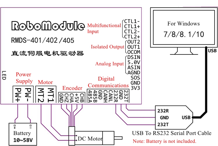
Attention:
- It is recommended to use a USB to RS232 serial cable with FT232RL as its main chip
- The drive is connected to the computer for debugging and setting, only the RS232 port can be used
- It is recommended to use the USB to RS232 serial cable, and the FT 232 chip version is recommended
- It is forbidden to use the CH340 serial line. The CH340 serial line does not meet the level standard specified by RS232. It is only reversed on the basis of TTL, and cannot be guaranteed.
Normal communication. Using it may also cause the debugging software to crash, and frequent errors in data transmission and reception, so it is forbidden to use it
- It is forbidden to use the PL2303 (Prolific) serial cable. The serial chip of PL2303 is unstable, and a large amount of wrong data may appear after working for a long time, which may cause the debugging software to freeze frequently, and there may be a certain probability that the computer will blue screen.
- If there is a serial cable, please insert the USB port of the computer in advance and check its type in the device manager. The different serial lines are displayed as follows in the device manager: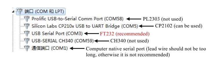
Package Included:
- 1 x Set of DC Servo Motor Driver
Note:
- Battery is not included.
- Other items pictured are not included in the package, for demonstration purposes only. Thank you for your understanding!


 + Raspberry Pi 5 4GB + 25m N10P Lidar + RGB Camera")

 PLUS Ackerman Robot Car High-End Version w/ Swing Suspension Basic Package without Lidar")