| Quantity | 3+ units | 10+ units | 30+ units | 50+ units | More |
|---|---|---|---|---|---|
| Price /Unit | $44.81 | $43.89 | $42.52 | $40.69 | Contact US |
 Crosbon Imported 3-Core 6mm² OFC Power Cable Soft OFC Speaker Wire (US Standard Plug, 1.5 Meters)
$37.31
Crosbon Imported 3-Core 6mm² OFC Power Cable Soft OFC Speaker Wire (US Standard Plug, 1.5 Meters)
$37.31
 Geekworm 5-in-1 RAB Holder Breadboard Holder ABS Base for Raspberry Pi 5 Ar-duino UNO R3 & Mega 2560
$11.37
Geekworm 5-in-1 RAB Holder Breadboard Holder ABS Base for Raspberry Pi 5 Ar-duino UNO R3 & Mega 2560
$11.37
 Portable Handheld Tesla Coil 3.0 PRO Version 0-500uS 7-level Adjustable Power Pulse Width (2600mAH meets 20000 arcs)
$51.66
Portable Handheld Tesla Coil 3.0 PRO Version 0-500uS 7-level Adjustable Power Pulse Width (2600mAH meets 20000 arcs)
$51.66
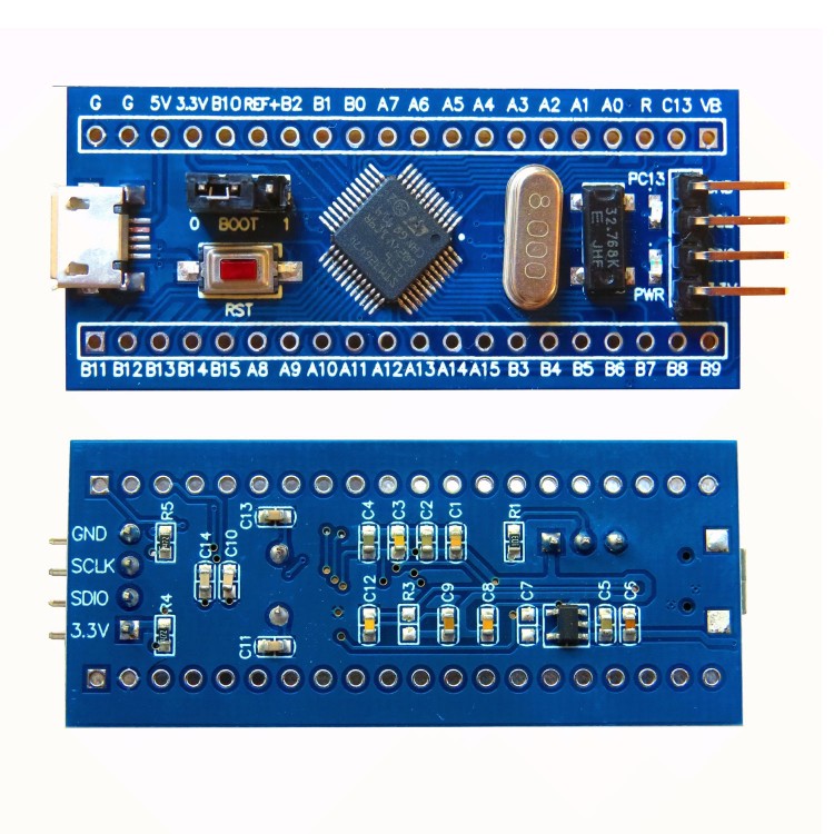
STM32G474CET6 Core Board Minimum System For Cortex-M4 G4 Development Board w/ USB-Micro Data Cable
Description:
This product is an core board for ARM-CORTEX-M4 based on STM32G474CET6 chip.
1. The core board provides the most basic circuits for the normal operation of the STM32G474CET6 chip, including external high-speed crystal oscillator (8MHz) circuit, power management circuit (ME6211C33M5G), debug interface (SWD mode), BOOT selection circuit, etc.
2. This core board provides close to all available port resources, including all I/O port resources except PF0, reset I/O port resources, BOOT selection port resources, etc.
3. The core board provides a power monitoring LED (PWR LED) and a chip running indicator (controlled by the PC13 pin in STM32G474CET6, if the pin is short, the PC13 pin is required, just disconnect the PC13_LED)
4. Power supply mode:
A. You can choose to supply power through the USB-Micro interface on the core board
B. Connect to the SWD interface through the debugging equipment for power supply (2.7V-3.6V)
C. Connect to the port (5v-12V) corresponding to the silk screen 5v through an external power supply
D. It is not recommended to use multiple power supply methods at the same time. Cross power supply may easily cause the core board or debugger to short-circuit and burn out
5. In order to save the volume of the core board, the core board provides the SWD program download/debugging interface, and supports the SW mode of JLINK, ST-LINK, DAPLINK and other common debuggers for debugging and program download
6. The core board provides the RTC clock crystal oscillator, and leads out the power interface required by the RTC (corresponding pins of the core board silk screen layer VBAT)
7. The core board provides a reset button for users to conveniently reset during device debugging (in addition, the reset pin is also led out, the core board silk screen layer R corresponds to the pin)
8. The core advantage of the core board is to provide users with rapid project deployment needs and as much internal chip resources as possible. Therefore, we did not add any modules on the core board that users may not use and users seize resources to truly experience the core board. Core value.
9. All the pins of the core board are led out through 2.54mm pitch holes. The corresponding 2.54mm pin headers are provided free of charge. The BOOT selection pins and the SWD program download/debugging interface have been soldered by default
Product Features:
- Small size. STM32G474CET6 core board is 53.34mm*22.86mm (i.e. 2100mil*900mil)
- Cost-effective
- Short development period
- Not seize chip resources
- Outstanding compatibility
- Compact size
Package Included:
- 1 x Set of STM32G474CET6 Core Board
Tests Before Delivery:
In order to ensure a good experience for customers, our store will designate test links with different characteristics for different modules, and strictly implement them before shipment. The test points of this product are as follows:
1. Power-on test, including power supply voltage regulation test and LED test;
2. Use SWD interface to test the program download on the STM32G474CET6 core board;
3. Test the connectivity of all pins of the STM32G474CET6 core board.


 PLUS Ackerman Robot Car High-End Version w/ Swing Suspension Raspberry Pi 5 8GB + N10P")