| Quantity | 3+ units | 10+ units | 30+ units | 50+ units | More |
|---|---|---|---|---|---|
| Price /Unit | $42.64 | $41.77 | $40.46 | $38.72 | Contact US |
 Finished HiFi Preamplifier Board DIY Audio Amplifier Board Replacement for Marantz HDAM Classic Preamplifier
$32.62
Finished HiFi Preamplifier Board DIY Audio Amplifier Board Replacement for Marantz HDAM Classic Preamplifier
$32.62
 Line Magnetic Audio LM-508IA 48W+48W Tube Amplifier Integrated Amplifier Tube Amp with Two VU Meters
$2,624.45
Line Magnetic Audio LM-508IA 48W+48W Tube Amplifier Integrated Amplifier Tube Amp with Two VU Meters
$2,624.45
 2x80W HiFi Digital Power Amplifier Board V1.6 Class D Amplifier Board for MERUS MA12070 with Toggle Switch
$33.44
2x80W HiFi Digital Power Amplifier Board V1.6 Class D Amplifier Board for MERUS MA12070 with Toggle Switch
$33.44
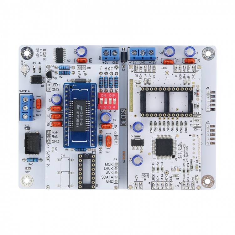
TDA1540 Driver Board Supports 256FS 384FS I2S Input CS8412CS-SOP SAA7030 OS Version
Description:
- The latest version adopts CS8412CS-SOP package. The functions are the same as the old version
- Data webpage (copy to browser and open): http://www.cdream5.com/htm/1540_DR.htm
- This board is stripped from the 1541 1540DAC previously designed by the webmaster. You can use this board to drive the TDA1540DAC directly. This board can be used to modify some old CD players; some old CD players such as CDM2 CDM4 and the like, bald head It is aging, but the internal DAC is normal, you can use this board to drive the built-in 1540, so that the CD function can use the residual temperature.
- The board has a high-precision PLL circuit and supports a digital output chip with 256fs output. Most digital receiving chips and I2S signals can support
How to use


Method 1. Connect the two sets of power supply +5V, +12V GND -12V needed on this board, remove the SAA7030 chip on the original board, and connect the digital signal output directly to the corresponding pins of SAA7030

Method 2. Connect the two sets of power supply +5V, +12V GND -12V needed on this board, remove the SAA7030 chip on the original board, and connect the digital signal output directly to the corresponding pin of the 1540 chip


Method 1. Connect the two sets of power supply +5V, +12V GND -12V needed on this board, remove the SAA7030 chip on the original board, and connect the digital signal output directly to the corresponding pins of SAA7030
Method 2. Connect the two sets of power supply +5V, +12V GND -12V needed on this board, remove the SAA7030 chip on the original board, and connect the digital signal output directly to the corresponding pin of the 1540 chip
Method 3: Remove SAA7030 on this board, this board is only connected to +5V power supply, this board is set to OS (16bit) mode (J7, J8, J10, J11, J12 disconnected), keep SAA7030 on the original board, cut off the original SAA7030 input signal wires 17, 18, 19, 20, 21 and other chip connection wires, connect 17, 18, 19, 20, 21 of SAA7030 on the module board to 12, 17, 18 of SAA7030 on the modified board ,19,20,21; this modification can only support up to 48K


")
