| Quantity | 3+ units | 10+ units | 30+ units | 50+ units | More |
|---|---|---|---|---|---|
| Price /Unit | $49.08 | $48.08 | $46.57 | $44.57 | Contact US |
 JHEMCU F405 Wing Flight Control INAV Firmware 5V 8A BEC Built-in Barometer for Fixed Wing FPV Racing Drones
$51.32
JHEMCU F405 Wing Flight Control INAV Firmware 5V 8A BEC Built-in Barometer for Fixed Wing FPV Racing Drones
$51.32
 A6 SE APM Opensource UAV Flight Control with Galvanometer Module and Note3 Ultra GPS for Pixhawk UAV Drones
$234.83
A6 SE APM Opensource UAV Flight Control with Galvanometer Module and Note3 Ultra GPS for Pixhawk UAV Drones
$234.83
 CUAV NEO 4SE High Precision Navigation Opensource GPS Positioning Module for U-blox M10 Satellite Receiving
$73.67
CUAV NEO 4SE High Precision Navigation Opensource GPS Positioning Module for U-blox M10 Satellite Receiving
$73.67
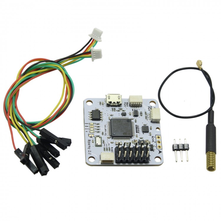
TL TauLabs Sparky2.0 Flight Control Receiver Quad-Rotor Multi Copter Mikrokop Flight Controller
Features:
- Runs Tau Labs (of course ;-). Same great flight performance you've come to expect and standard features. Open source hardware! (also of course)
- More powerful processor. Uses an STM32F4 running at 168 Mhz with increased memory and flash. This is useful for storing and flying longer waypoint sequences and running more complicated code like picoC scripting.
- More connectivity. (RCVR, Flexi, Main, I2C Aux). This is really useful if you want to have an external mag, gps, and spektrum receiver or other things like OSD.
- Flash chip which can be used to store flight plans, picoC code, or logging
- RFM22b radio can be used for telemetry or with openLSRng. The receiver antenna uses the same * U.Fl. connector that Freedom has. I really like this because it is very small and you can easily add an SMA break out cable or a whip antenna. It also has just the right amount of tension - strong enough to hold together in flight but in a crash it will disconnect and not damage the board. There is a small hole at the front to provide strain release for a whip antenna that you can just pass through and solder straight to the RFM22b for minimal configurations.
OpenLRS support: directly control from your OpenLRSng radio if you don't want a TauLink. Also OpenLRS beacon for finding lost frames.
- FrSky Telemetry support for either Sensor Hub or S.Port style receivers.
- Four buffered outputs to drive either LEDs (indicate flight status) or brushed motors. I'm really excited to have different colored LED strips turn on to indicate the direction it is facing relative to home.
- DAC output for VTX audio telemetry. I'd like to be able to add some prerecorded audio sounds so the headphones can provide useful information for FPV.
- Dual analog input for voltage and current monitoring. The DAC output can also be used as an analog input.
- CAN Bus which is very useful for talking to external devices like the brushless gimbal to coordinate POI tracking or control the gimbal pitch from transmitter. Also CAN enabled ESCs are coming out which will allow serious improvements in flight quality.
- Full sensor suite of course. MS5611 baro and MPU-9250 combined gyro/accel/mag. I was really conflicted on switching from the MPU-9150 to the MPU-9250. However, being able to utilize an SPI bus which is much better handled on the processor side made it worthwhile.
- Optional single sided assembly - the necessary things to fly are all on the top of the board. The bottom has the - CAN bus connector, RFM22b, antenna, external LED drivers. So if you just want a more powerful flight controller with more memory and CPU over Sparky it's still single sided.
Top connectors:
- Main Port: USART1. Capable of Telemetry, GPS, DSM, Debug, ComBridge, MavLink, HOTT, FrSky Sensor, Lighttelemetry, PicoC
- FlexiPort: USART3/I2C2. Similar to MainPort but also capable of external I2C.
- Rcvr: USART6. Convenient connection for receivers with selectable power between external power or 3.3V. - PPM, S.Bus, DSM, HOTT.
- Analog: current, voltage, RSSI or DAC output
- Servo outputs: 6 PWM headers. capable of traditional PWM or OneShot.
Bottom connectors:
- Radio: U.Fl. header for RFM22b module. Typically 433 MHz module. Either use a433Mhz U.FL ferrite - Antennaor433Mhz U.FL Helical antenna
- Power selector: select power for the Rcvr header by soldering either the 3.3V bridge or 5.0V (which passes power from the external power supply such as BEC)
- CAN: CAN bus header. Used for connecting to external devices such as SparkyBGC or TauOSD+VTX.
- I2C: auxiliary I2C bus (I2C1). This is the same bus that the MS5611 is connected to. can be used for external mag.
- LED: 4 buffered PWM outputs. These are passed through an N-channel FET. Can power external LEDs or brushed motors (rated for 3A)
Using buffered PWM outputs:
These outputs can handle more current and can be used for directly controlling external LEDs. These are mapped in software to PWM 7-10 and are available on the "LED" header on the back which is a 6 pin JST-SH header. They use an N-Channel FET so when the PWM pulse is high the FET is on and pulling the output towards ground.
- The power pin is connected to the power on the servo headers, so you can use this power pin to drive your LEDs if they are 5V tolerant and the BEC can handle the current.
- If you want to use the outputs to directly control a servo or ESC you either need to remove the output FETs and solder wires to bypass them (photos to come) or use an external board that inverts them again
Note: Does NOT come with Antenna.
Package included:
- 1 x TauLabs Sparky2.0


")
")


")