| Quantity | 3+ units | 10+ units | 30+ units | 50+ units | More |
|---|---|---|---|---|---|
| Price /Unit | $24.42 | $23.92 | $23.18 | $22.18 | Contact US |
 High Precision 17-340Nm Torque Tester Digital Display Torque Meter Support Peak/Track Mode Switch
$33.33
High Precision 17-340Nm Torque Tester Digital Display Torque Meter Support Peak/Track Mode Switch
$33.33
 High Precision 10-200Nm Torque Tester Digital Display Torque Meter Support Peak/Track Mode Switch
$30.22
High Precision 10-200Nm Torque Tester Digital Display Torque Meter Support Peak/Track Mode Switch
$30.22
 High Precision 1.5-30Nm Torque Tester Digital Display Torque Meter Support Peak/Track Mode Switch
$30.22
High Precision 1.5-30Nm Torque Tester Digital Display Torque Meter Support Peak/Track Mode Switch
$30.22
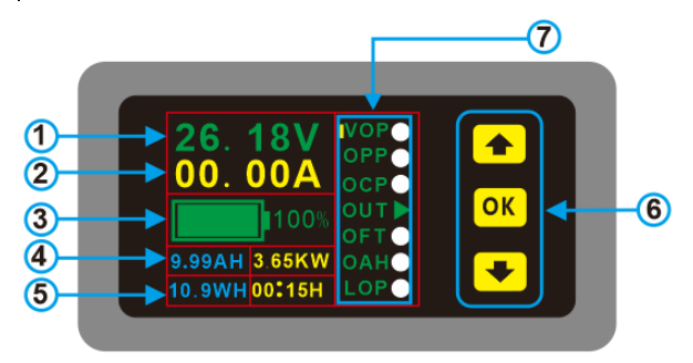
① Voltage
② Current
③ Capacity percentage and progress bar
④ AH (blue) and power (yellow)
⑤ WH (blue) and time (yellow)
⑥ Buttons
⑦ Menu to choose protections

Wiring:
The
circuit diagram below shows the circuit in discharge mode. When it is
charging, you only need to replace the load with a charger without
changing the circuit. The current direction enters from the front of the
transformer, and the current is negative, that is, the remaining power
of the instrument decreases; otherwise, the current is positive, and the
remaining power increases.
1. Figure 1 shows the wiring mode of the power supply without the relay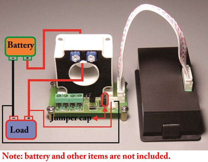
When
in use, the positive and negative poles of the battery correspond to
the positive and negative poles of the "BAT" on the expansion board
respectively. Make sure the wiring is in the correct direction. Pass one
of the positive or negative wires from the battery to the load through
the round hole of the Hall transformer, then connect the jumper cap to
J4, and finally plug the positive and negative terminals of the battery
into the "BAT" on the expansion board and then power on.
2. Figure 2 shows the wiring mode of independent power supply without relay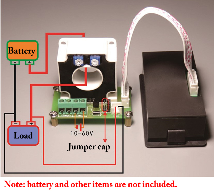
When
in use, the positive and negative poles of the battery should
correspond to the positive and negative poles of the "BAT" on the
expansion board. Be careful not to reverse it. First, pass one of the
positive or negative wires from the battery to the load through the hole
of the Hall transformer, and then connect the jumper cap to J3.
Finally, insert the terminals of the positive and negative poles of the
battery into the "BAT" on the expansion board. Connect to Vext when
externally powered. Pay attention to the positive and negative external
power supply voltage range of 10-60V, do not connect wrongly and
reversely.
3. Figure 3 shows the wiring mode of the independent power supply with relay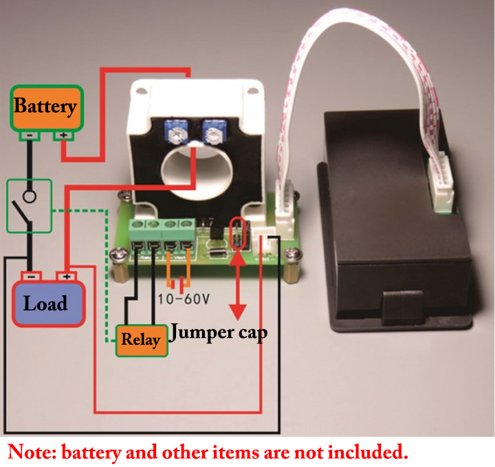
In
use, battery wiring should correspond to the positive and negative
poles of "BAT", and do not reverse it. First, pass one of the positive
or negative wires from the battery to the load through the round hole of
the Hall transformer, then press the jumper cap at J3, and then connect
the relay. Finally, insert the terminals of the positive and negative
poles of the battery into the "BAT" on the expansion board, and connect
the external power supply to "Vext". The external power supply voltage
range is 10-60V, be careful not to connect it wrongly. (Note: The
independent power supply matches the relay voltage)


")


