| Quantity | 3+ units | 10+ units | 30+ units | 50+ units | More |
|---|---|---|---|---|---|
| Price /Unit | $20.39 | $19.98 | $19.35 | $18.52 | Contact US |
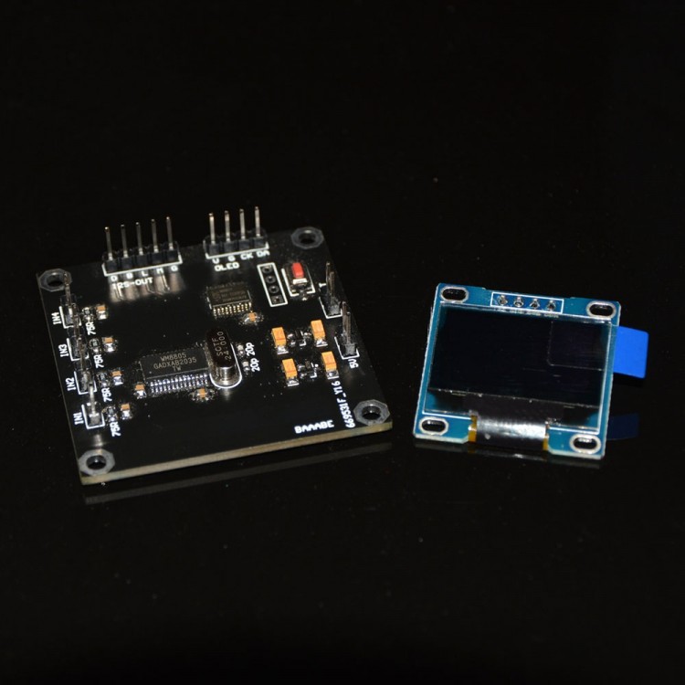
WM8805 Audio Receiver Board SPIDF to I2S + 0.96" OLED Screen to Display Sampling Rate up to 192K
Description:
WM8805 digital audio receiver chip has many functions. It supports multiple 24bits/192KHz SPDIF inputs. Its built-in advanced phase-locked loop with jitter attenuation enables clock cycle jitter to be less than 50ps RMS. It automatically detects the sampling frequency and automatically identifies non-audio data. It also has hardware control, and software control mode (this solution adopts soft control mode)! It supports 32K, 44.1K, 48K, 88.2K, 96K, 176.4K and 192K sample rates, supports 16-24bit data and support multiple data format output.
Hardware Interface Description:
* IN1-IN4 are standard SPDIF signal input ports (Looking at the character from the front, the left and right pins are GND and signal input, respectively)
* The interfaces marked 5V and G are power supply ports, and their voltage range is 4.5-5.25V DC. Exceeding the voltage range and reverse connection of power supply can cause permanent damage to the board
* I2S-OUT interface is an I2S signal output port
The I2S Output Port is Defined as Follows:
* D is DATA; B is BCK; L is LRCK; M is MCLK; G is GND.
* OLED port is used to connect to the display, and the V port is connected to the VCC of the display; GND of G port display screen; CK is connected to the SCK or SCL of the display; The DA is connected to the SDA of the display.
* BUT interface is an external button interface, and its function is the same as the button on the board, which is convenient for external buttons to use when installing (self-reset button is required).
* When used normally, the BUT/ button is used to switch the signal input of IN1-IN4 cyclically; In addition, the button can be used to switch the data format of the I2S output signal. Switching method: first press and hold the button without releasing it and then power on the board, after a few seconds it will enter the formatting mode. Switch the output format by pressing the key and exit the setup mode by pressing and holding the button!
Specifications:
* This board supports output formats including I2S, LJ left alignment format, RJ16, RJ20, and RJ24
* PCB board size: 4.826 x 4.826cm/1.9 x 1.9"
* Screw hole distance (center to center): 4.267 x 4.267cm/1.7 x 1.7"
Package Included:
* 1 x Board
* 1 x 0.96" OLED Display