| Quantity | 3+ units | 10+ units | 30+ units | 50+ units | More |
|---|---|---|---|---|---|
| Price /Unit | $14.73 | $14.43 | $13.98 | $13.38 | Contact US |
 G1009 10-inch Embedded HD Industrial Monitor 1024x768 Hook Mount TFT Display with BNC/VGA/AV/HDMI-compatible Ports
$109.57
G1009 10-inch Embedded HD Industrial Monitor 1024x768 Hook Mount TFT Display with BNC/VGA/AV/HDMI-compatible Ports
$109.57
 G121SN01 V3 Color Active Matrix LCD Display Panel Designed for Various Industrial Applications
$88.42
G121SN01 V3 Color Active Matrix LCD Display Panel Designed for Various Industrial Applications
$88.42
 RTU-307D NET-07D 8AI-8DI-8DO Data Acquisition Module IO Module (RS485+RS232) for Industrial Use
$76.89
RTU-307D NET-07D 8AI-8DI-8DO Data Acquisition Module IO Module (RS485+RS232) for Industrial Use
$76.89
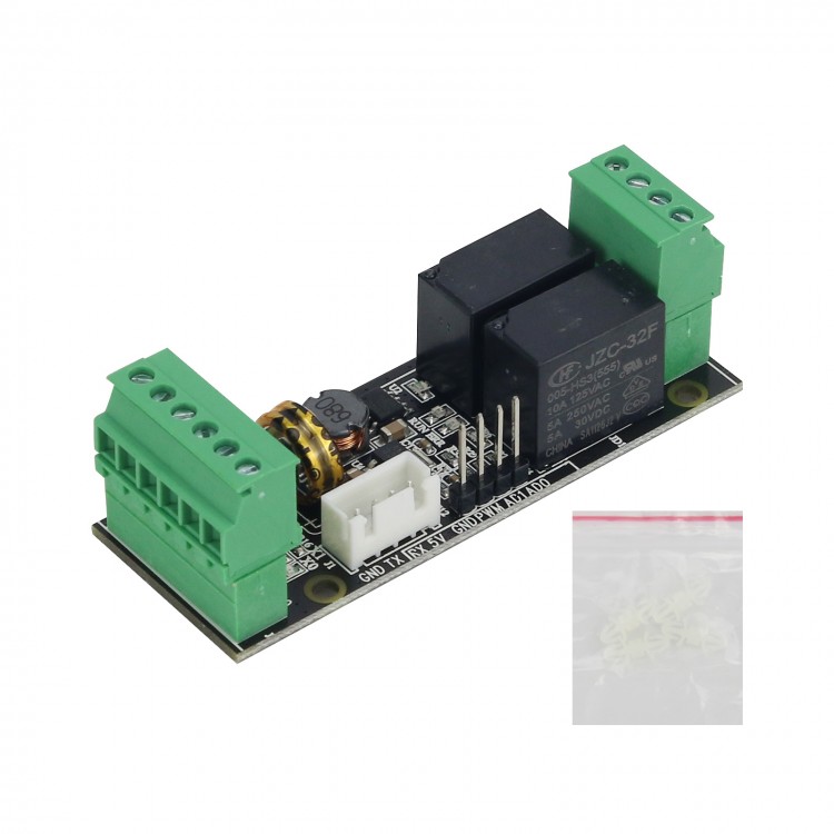
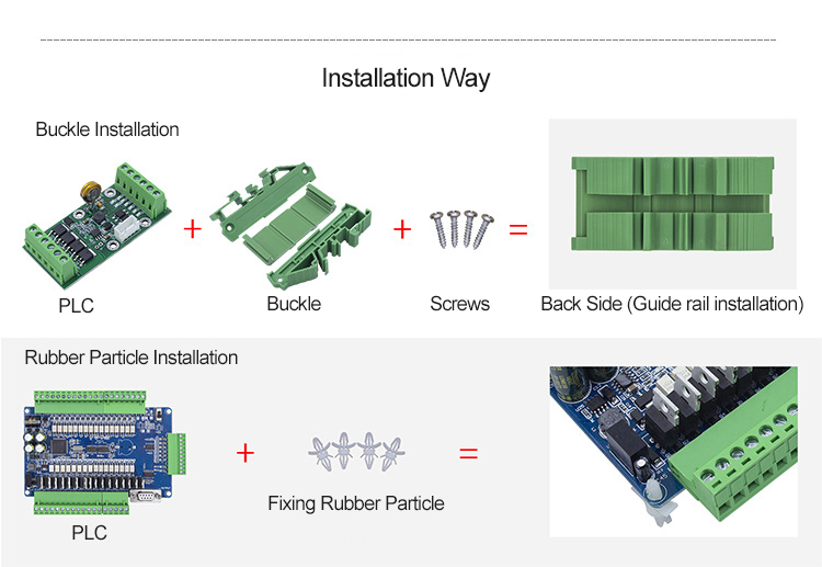
WS2N-6MR-S PLC Controller Simple Programmable Logic Controller For Industrial Automation Control
Advantages:
- Compact size
- Cost-effective
- Support analog quantity
- Support PWM
Features:
- Original chip
- Stable performance
- Online download
- Online monitoring
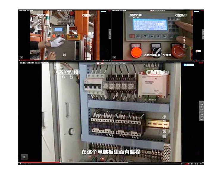
- Can be used in various industrial automation control
- Suitable for metallurgy, printing, chemicals, plastics, building materials, home furnishing, packaging, textiles, food
Specifications:
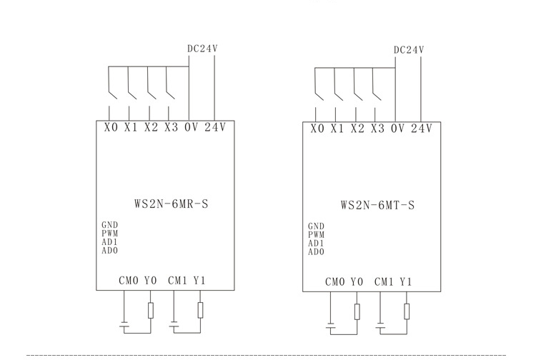
- Model: WS2N-6MR-S
- Input point: 4
- Output point: 2
- Output type: Relay
- Output current: 5A
- Load: 24V, 220V
- High-speed counting: 2/3K
- Pulse output: None
- Analog quantity input: Optional 2AD 0-10V
- Analog quantity output: None
- For MODBUS: None
- Clock: None
- Base: Optional
- Dimensions: 73* 27 mm (LxW)
- Hole spacing: 21.8*52.5 mm (LxW)
- Size with optional base: 86*31.4*48.4 mm (LxW)
Package Included:
- 1 x Set of PLC Controller
Summary of Component Number Assignment and Function:
Auxiliary Relay:
General use: M0-M511, 512 points
For holding: M512-M3071, 2559 points
Special use: M8000-M8255, 256 points
Status Register:
General use: S0-S127, 128 points
Storage: S128-S899, 772 points
Timer:
100MS: T0-T199, 200 points
10MS: T200-T245, 46 points
1MS cumulative type: T246-T249, 4 points
100MS cumulative type: T250-T256, 6 points
Counter:
16-bit increment (for general use): C0-C15, 16 points
16-bit increment (for holding): C16-C99, 84 points
32-bit reversible (generally used): C200-C219, 20 points
32-bit reversible (for holding): C220-C234, 15 points
32-bit reversible (for high-speed retention): C235-C247, 13 points
Data Register:
16-bit general use: DO-D511, 512 points
16-bit retention: D512-D998, 487 points
16-bit special use: D8000-D8255, 256 points
For 16-bit indexing: V0-V7, Z0-Z7, 15 points
Nested Pointers:
For skip subroutine, branch: P0-P127, 128 points
Main control: N0-N7, 8 points
Constant:
Decimal (K): 16 bits -32768 to +32767 (32 bits -2147483648 to +2147483647)
Hexadecimal (H): 16 bits: 0~FFFFH (32 bits: 0~FFFFFFFFH)
Special Soft Component Description:
M8000: RUN monitoring (always open during RUN)
M8002: Initialization pulse (normally open scan cycle flag)
M8004: Error prompt (PLC error)
M8012: 100ms clock (oscillate with 100ms period)
M8014: 1min clock (oscillate with 1min period)
M8021: Dislocation mark
M8029: Y0 instruction execution end
M8030: Y1 instruction execution ends
M8001: RUN monitoring (normally closed during RUN)
M8003: Initialization pulse (normally closed scan cycle flag)
M8011: 10ms clock (oscillate with 10ms period)
M8013: 1s clock (oscillates in 1S period)
M8020: Zero mark (operation mark for application instructions)
M8022: Carry flag
M8040: Transfer prohibited
Instruction List:
27 Basic Sequence Commands:
[LD]: Take
[ANI]: and reverse
[OUT]: Output
[ANB]: Circuit block and
[MRD]: Read stack
[LDP]: Take the rising edge of the pulse
[ANDF]: and pulse falling edge
[RET]: Return
[MC]: Master
[LDI]: Take reverse
[OR]: or
[SET]: Set
[ORB]: loop block or
[MPP]: Pop
[LDF]: Take the falling edge of the pulse
[ORP]: Or pulse rising edge
[PLS]: rising edge pulse
[MCR]: Master control reset
[AND]: and
[ORI]: or reverse
[RST]: Reset
[MPS]: Push to stack
[INV]: Invert
[ANDP]: and pulse rising edge
[ORF]: Or pulse falling edge
[PLF]: Falling edge pulse
[END]: End
1 Step Instruction:
[STL]: Step ladder diagram
Application Instruction List:
Procedure Flow Chart:
FNC No.: 00. CJ: Conditional jump
FNC No.: 01. CALL: Subroutine call
FNC No.: 02. SRET: Subroutine return
FNC No.: 03. FEND: End of main program
FNC No.: 04. WDT: Watchdog timer
FNC No.: 05. FOR: Starting point and number of cycles
FNC No.: 06. NEXT: End of the cycle
Transmission and Comparison:
FNC No.: 07. MOV: Send
FNC No.: 08. BIN: Convert BCD code to binary
FNC No.: 09. CML: Inverted transmission
FNC No.: 10. CMP: Compare
FNC No.: 11. ZCP: Interval comparison
FNC No.: 12. FMOV: Multicast
Arithmetic and Logical Operations:
FNC No.: 13. ADD: Binary addition operation
FNC No.: 14. SUB: Binary subtraction
FNC No.: 15. MUL: Binary multiplication
FNC No.: 16. DIV: Binary division operation
FNC No.: 17. INC: Binary plus 1 operation
FNC No.: 18. DEC: Binary minus 1 operation
FNC No.: 21. WAND: Word logic and
FNC No.: 22. WOR: Word logical OR
FNC No.: 23. WXOR: Logical exclusive OR
FNC No.: 23. NEG: Make up
Cycle and Displacement:
FNC No.: 24. ROR: Shift right loop
FNC No.: 25. ROL: Shift left loop
FNC No.: 26. RCR: Right shift loop with carry
FNC No.: 27. RCL: Shift left loop with carry
Bit Data Processing:
FNC No.: 28. ZRST: Mass reset
High-Speed Processing:
FNC No.: 29. PWM: Pulse width modulation output
FNC No.: 30. PLSY: Specified frequency pulse output
FNC No.: 31. PLSR: With acceleration and deceleration pulse output
Convenient Instructions:
FNC No.: 32. ALT: Alternate output
Contact Comparison:
FNC No.: 33. LD: (S1)=(S2) when the starting contact is on
FNC No.: 34. LD>: (S1)>(S2) when the starting contact is on
FNC No.: 35. LD<: (S1) <(S2) when the starting contact is on
FNC No.: 36. LD<>: (S1)<>(S2) when the starting contact is on
FNC No.: 37. LD≦: (S1)≦(S2) When the starting contact is on
FNC No.: 38. LD≥: (S1)≥(S2) when the starting contact is on
FNC No.: 39. AND=: (S1)=(S2) when the series contact is on
FNC No.: 40. AND>: (S1)>(S2) when the series contact is on
FNC No.: 41. AND<: (S1)<(S2) when the series contact is on
FNC No.: 42. AND<>: (S1)<>(S2) when the series contact is on
FNC No.: 43. AND≤: When (S1)≤(S2), the series contacts are connected
FNC No.: 44. AND≥: When (S1)≥(S2), the series contact is on
FNC No.: 45. OR=: (S1)=(S2) when the parallel contacts are connected
FNC No.: 46. OR>: (S1)>(S2), the parallel contacts are connected
FNC No.: 47. OR<: When (S1)<(S2), the parallel contacts are connected
FNC No.: 48. OR<>: (S1)<>(S2), the parallel contacts are connected
FNC No.: 49. OR≤: When (S1)≤(S2), the parallel contacts are connected
FNC No.: 50. OR≥: When (S1)≥(S2), the parallel contacts are connected
Command List is Not Supported in this Version:
1. WDT: Watchdog timer refresh
2. CML: Inverted transmission
3. XCH: Exchange
4. FMOV: Multicast
5. SMOV: Bit transfer
6. NEG: Find two's complement
7. REF: Input and output refresh
8. REFF: Input filter time adjustment
9. MTR: Matrix input
10. HSCS: Compare set (for high-speed counting)
11. HSCR: Comparison reset (for high-speed counting)
12. IST: State initialization
13. ABSD: Cam control (absolute)
14. INCD: Cam control (incremental)
15. DSW: BCD digital switch input
16. SEGL: Seven-segment time-sharing display
17. FROM: BFM read
18. TO: BFM write
19. CCD: proofreading
20. VRRD: Potentiometer variable input
21. VRSC: Potentiometer variable interval
22. ABS: ABS current value read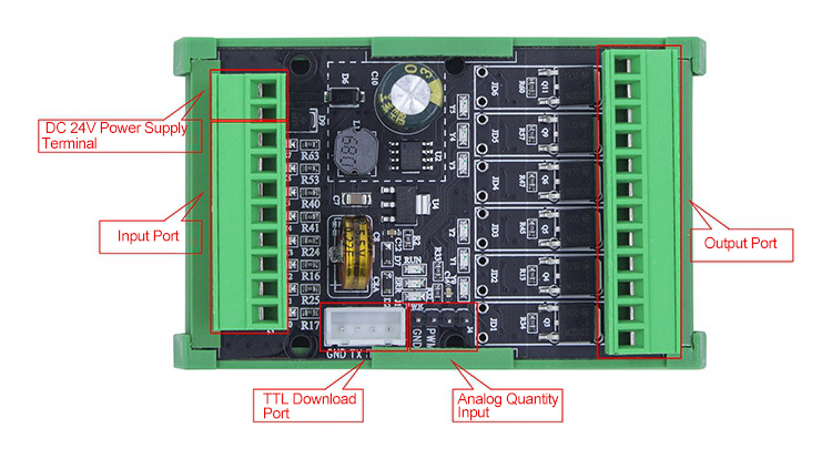
Application Example: