| Quantity | 3+ units | 10+ units | 30+ units | 50+ units | More |
|---|---|---|---|---|---|
| Price /Unit | $78.53 | $76.92 | $74.52 | $71.32 | Contact US |
 0-1MPa 4-20mA Diffused Silicon Pressure Sensor (Cable Outlet Type) for Water Liquid Gas and Oil
$36.21
0-1MPa 4-20mA Diffused Silicon Pressure Sensor (Cable Outlet Type) for Water Liquid Gas and Oil
$36.21
 4-20mA Diffused Silicon Pressure Sensor (with Digital Display) for Water Liquid Gas and Oil Pressure
$63.42
4-20mA Diffused Silicon Pressure Sensor (with Digital Display) for Water Liquid Gas and Oil Pressure
$63.42
 4-20mA Diffused Silicon Pressure Sensor (Connector for Hirschmann) for Water Liquid Gas Oil Pressure
$30.38
4-20mA Diffused Silicon Pressure Sensor (Connector for Hirschmann) for Water Liquid Gas Oil Pressure
$30.38
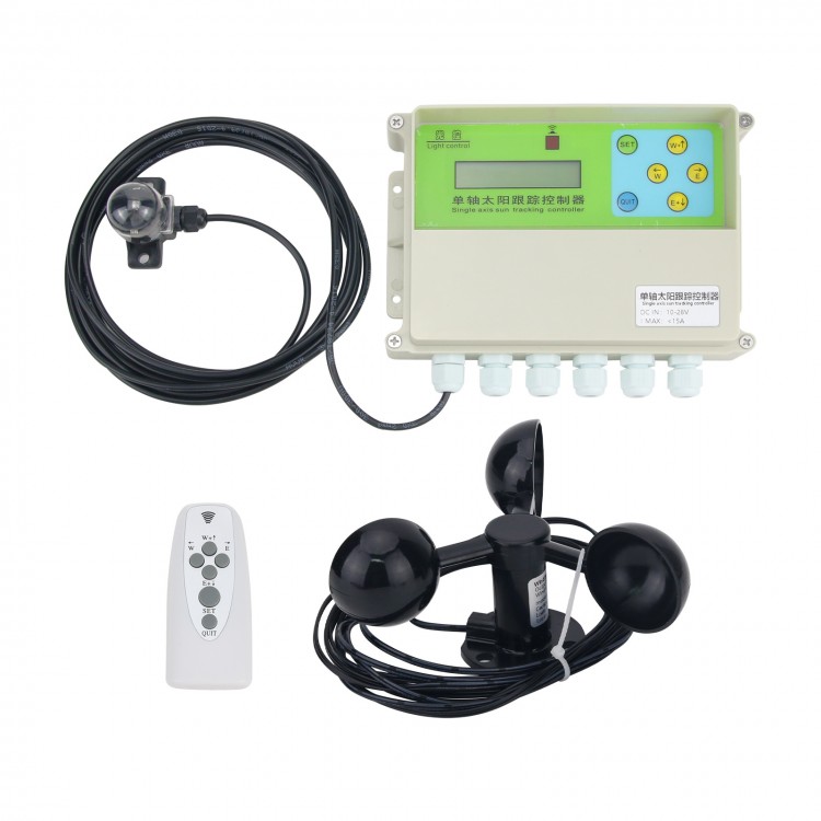
XMYC-1 Single Axis Solar Tracker Controller 12-24V Solar Tracking + Wind Speed Sensor Remote Control
Description:
This is a simple solar tracking controller. It is suitable for a single-axis mechanical platform driven by a DC brush motor to track the sun. The platform type can be a flip type or a rocking type. The applicable voltage is 12-24V, and the maximum current is less than 15A (default 10A fuse).
Package Included:
- 1 x Solar Tracker Controller
- 1 x Remote Control
- 1 x Wind Speed Sensor
Note:
- Other items pictured are not included, for demonstration purposes only. Thank you for your understanding!
- Batteries are not included. 2pcs AAA batteries are needed for the remote control.
User Manual of XMYC-1 Single-Axis Solar Tracking Controller:
This
controller is a single-axis solar tracking controller. It uses
dedicated internal and external direction detection heads to detect
sunlight direction. The detection head signal is analyzed and judged by
the single-chip microcomputer circuit on the controller. And the process
of tracking the sun is carried out by the corresponding motor on the
controller platform through the relay combination on the circuit board.
At
the same time, you can lay it flat in case of wind (wind speed sensor
needs to be purchased), and it can return to the position at nights.
English LCD screen is used to display the corresponding parameters, and
the parameters can be set by the buttons on the controller or the
buttons of an infrared remote control (remote control needs to be
purchased).
The corresponding platform requirements of this
controller are oblique single-axis platforms or column rotating
platforms, and the driving motor of the platform is a DC brush motor,
with a motor voltage of 12 or 24V and a current of less than 15A. Limit
switches should be available in both directions of the platform.
Main Accessories of Solar Tracking Controller:
1. Main controller: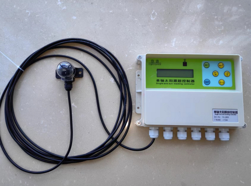
Mounting
hole of the main controller is 4MM/0.2"; Hole spacing from left to
right is 174MM/6.9". Hole spacing from top to bottom is 60MM/2.4".
It
uses a waterproof box as the shell. It has 6 waterproof interfaces for
line connection, and all the line connections on the motherboard adopt
terminals for wiring, and the corresponding parameter status on the
display screen can be seen through the upper cover, and various
operations can be performed on the controller through the buttons.
2. Sunlight sensor: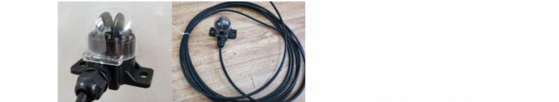
The
sensor is a one-piece structure with a transparent shell. Through the
shielding of the fan-shaped module in the middle, the different sunlight
radiation voltages generated in two directions, inside and outside, are
transmitted to the motherboard through a 3-core cable. The sensor can
be fastened with two M6 bolts, 40mm/1.6" apart. The whole is installed
in a transparent plastic dome, which has a certain dustproof and
rainproof function, and can meet the service life of ten years (with
3m/9.8ft cable by default). When it is tracking in north-west direction,
the outlet hole is facing south.
3. Wind speed sensor (optional):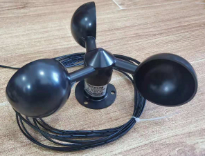
Wind
speed sensor is used to detect the wind speed of the environment. When
the wind speed reaches the protection value set by the controller,
platform will be controlled and driven to a position that can shelter
from the wind. The default wind speed sensor has a cable 3 meter/9.8 ft
in length. (If you want to configure the wind speed sensor by yourself, a
voltage signal type wind speed sensor is needed)
4. IR remote control (optional; effective range: 8m/26.2ft):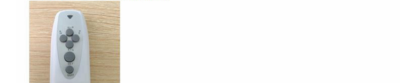
Note: The remote control is powered by 2pcs AAA batteries which are not included in the package.
5. Proximity limit switch (optional):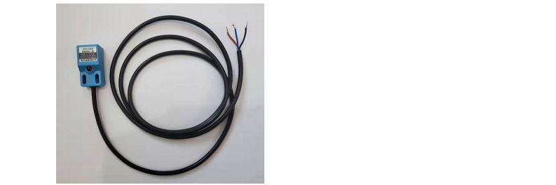
The limit signal can be detected and fed back to the controller. The length of the line is 1.2m/3.9ft.
Functions of Controller Board: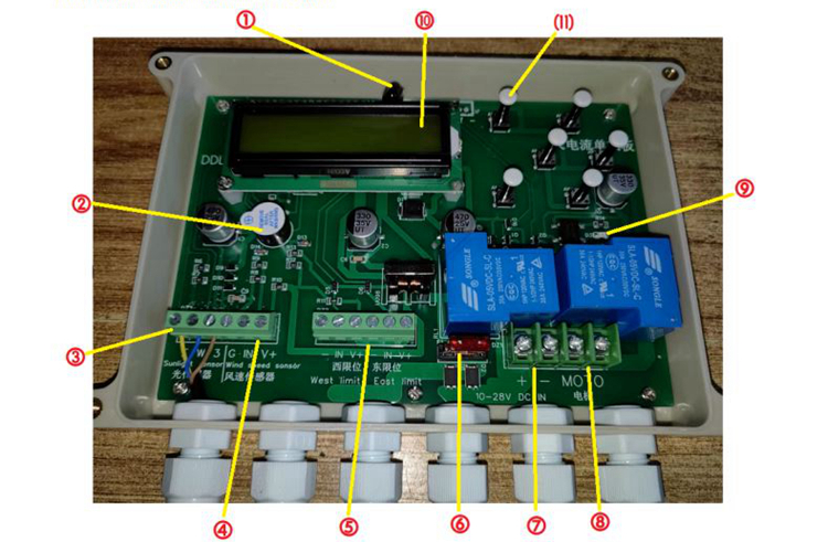
1. Remote control receiver
2. Buzzer
3. Sunlight sensor
4. Wind speed sensor
5. Limit terminals (from left to right: ground, west limit signal, power supply +, ground, east limit signal, power supply +)
6. Fuse (default 10A)
7. Power supply input (DC 12-24V, positive end on the left side and negative end on the right)
8. Motor output
9. Output indicator light
10. Display screen
11. Operation button
Installation Method:
Installation of sunlight sensor:
The
detection sensor is installed on the plane of the platform and moves
with the platform. When the platform is centered, it is not parallel to
the platform plane, but to the ground plane. At the same time, when the
platform is centered and placed flat, the outlet hole on the detection
head should correspond to the south of the geography (referring to the
east-west tracking).
The sensor should be mounted on the eastern edge of the north side of the platform as much as possible.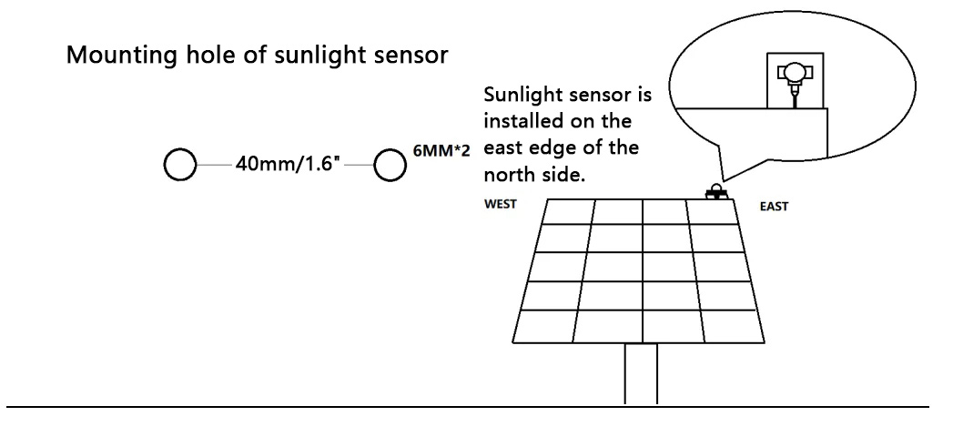
Installation of main controller:
The
main control box should be installed near the base post of the
platform, and does not need to move with the platform. Try to make sure
it's protected from rain, sun and other influences. The outlet hole
faces downwards to prevent rainwater from flowing in. The installation
should be located in a position which facilitates observation and
operation.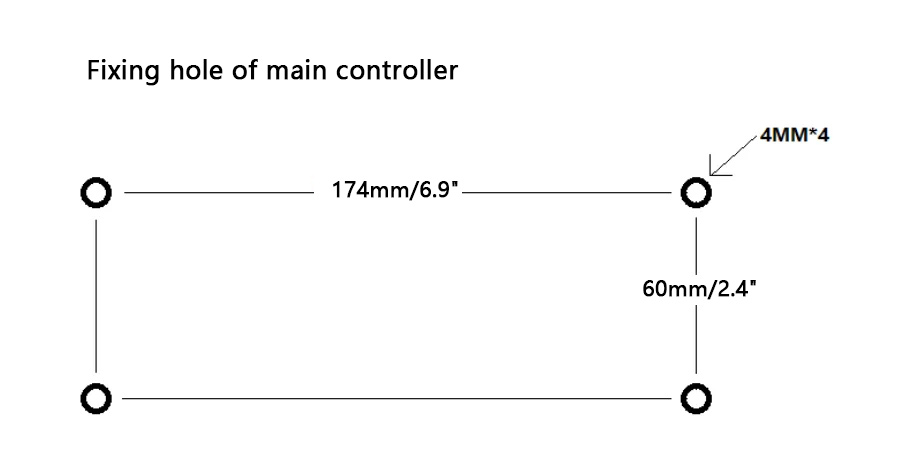
Installation of wind speed sensor:
-
The wind speed sensor should be installed near the platform, where it
can be effectively blown by the wind. Keep away from walls and floors. A
column can be used to support and mount the wind speed sensor.
- Wire the wind speed sensor to the main controller according to the mark, leaving room and installing it firmly.
-
The wiring method of our wind speed sensor: black wire with white
stripes to connect signal input IN, black wire to GND, and V+ power
supply terminal disconnected.
- If you are using a wind speed sensor
from another manufacturers, distinguish the V+, - and signal. Just
follow the instructions for access. The wind speed sensor terminal V+ on
this controller board is the power supply voltage (12-24V). The signal
output must be voltage type and the signal range must be less than 5V.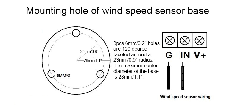
Wiring Method of Limit Switch:
If
you use a linear actuator with an internal limit, you don't need to
install a limit switch, otherwise the limit switch is essential, and
there are three ways to limit the position.
Method A: External
limit switch is used. And the method of external limit is as follows: a
micro switch with normally closed contact is arranged at the position
that needs to be limited at both ends of the platform, and the power
supply circuit of the corresponding motor is directly controlled to
achieve the limit, as shown in the following figure: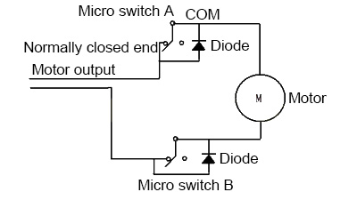
It is necessary to pay attention to whether the carrying current capacity of the limit switch is sufficient.
Method
B: The limit signal is introduced into the controller to achieve the
limit, then the limit switch with normally open contact needs to be
used. When a certain direction reaches the limit, the switch will be
topped, the switch will be closed and conducted, the ground of the limit
terminal will be shorted with the terminal in the corresponding
direction, and the output of the direction will be stopped at this time.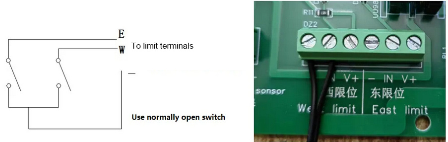
Method
C: This controller can also be connected to a three-wire NPN type
proximity switch. When using this kind of switch as a limit, the power
supply + end can be connected to the + end of the limit terminal, and
the other wiring is the same as that of method B (When purchasing
proximity switches in our company, the wiring definition: brown: +;
blue: -; black: limit signal). Note that the top is a sensing area. When
there is metal within 5mm, the limit signal will be output.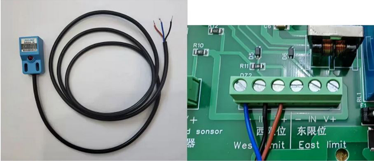
In
the case of separate power supply without connecting the controller
board, the drive motor of the platform should enable the smooth movement
of the platform within the corresponding range. In this case, the motor
can be connected to the motor terminal of the corresponding shaft on
the control board.
Debugging:
After confirming that the
sunlight sensor, wind speed sensor, limit, and motor are connected, you
can connect the power supply to the control board for debugging. The
power supply voltage is 12V or 24V (subject to the rated voltage of the
motor used). The power supply current should meet the maximum current
demand of the motor.
When the power is turned on, the controller should be powered to work, and the display should show:
The controller then will enter various states based on specific sensor feedback parameters.
Attention:
The screen backlight can be lit by pressing a button, and the backlight
will turn off after a 10-second delay. If you need to turn on the
backlight of the screen for a long time, you can turn on and off the
backlight by pressing and holding the QIT button for five seconds.
But
at this point, we should first test whether the orientation of the
motor is correct. So you have to go into the manual test first. Pressing
the SET button once will take you to the following manual page (MT):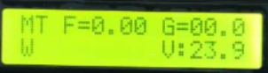
At
this time, buttons →/← control the platform to move east/west
respectively, and buttons ↓/↑ can control the platform to move east/west
by locking, and stop when you press the button again. At the same time,
the screen will display E/W to indicate the direction of movement. If
the direction of action of the platform does not match the direction of
manual control, the corresponding wiring should be changed. Test the
full range of activity of the platform with manual functions, including
limit status. Once all the tested functions are normal, you can proceed
with the next steps.
When you manually control the platform, the
corresponding output indicator light will turn on. Press the QUIT button
to exit the manual control mode.
Parameter Settings:
Once
we have made sure that the motor is wired correctly, we move on to the
parameter settings. Carry out the necessary checks and settings on some
parameters. When the interface is not manually controlled, press and
hold the SET button for five seconds and release the button, and the
device will enter the parameter setting page:
Attention: In the
following parameter setting interface, you can switch the parameter
options by pressing button →/←. Press button ↓/↑ to add/subtract
parameters, and press and hold the ↓/↑ button to quickly add/subtract
parameters. Press the QUIT button to exit and save the parameters. In
order to facilitate your understanding of the meaning of the parameters,
the following parameters are not presented in order. Please check the
actual settings by yourself.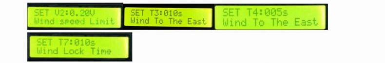
V2/T3/T4/T7: parameters related to wind speed protection.
When
the signal voltage from the wind speed sensor is higher than V2, the
device will enter the wind speed protection control state. It will
immediately drive the platform to the west T3 time, and then executes
the platform to the east T4 time. After performing the above process, T7
time is the holding time. During T7 time, the unit will remain in
standby mode. If the wind speed continues to exceed V2, the T7 time will
repeated. If the wind speed is lower than V2, the device will exit the
wind speed protection state after the T7 time ends. If the weather is
cloudy during the T7 countdown after the wind speed protection action is
executed, the device will lock and will not exit the wind speed
protection state.
By setting the above parameters reasonably, the
platform can be executed to the angle and position desired by users
when the wind speed exceeds the limit.
V1/V3/TX parameter meaning:
When
the voltage detected by the sunlight sensor in either direction is
higher than V3, the device thinks that it is sunny and the device will
time it. If detected voltage continues to be higher than V3 for 10
seconds, the device will enter the sunny tracking state. The controller
will control the motor movements of each axis to align with the sun. V1
is the tracking accuracy. The lower the value, the higher the accuracy.
However, the mechanical accuracy of the platform is required to reach a
certain level.
In the process of automatic tracking of the sun,
an interval time (TX) is set to avoid frequent repeated tracking caused
by small light changes when the sun is aligned. That is, after aligning
with the sun, the axis will enter the sleep time, and after this time,
the device will re-detect the position of the sun for tracking. The sun
moves very slowly, so setting intervals can save energy.
TX: The intermittent waiting time to enter when aligned with the sun.
By
setting the above parameters reasonably, it can ensure that the
controller can quickly and accurately track on sunny days. Note that the
time parameter (T) is in seconds. The threshold value (V) is measured
in voltage (V).
T8/T9/T10
parameter setting: the setting of platform homing parameters on cloudy
or night days. When the sunlight detector detects that the voltage in
either direction is lower than V3, it will judge that the sunlight is
weak. At this point, the device will sleep in place and enter T18
countdown (seconds). During this countdown time, if the sunlight value
has not returned to be over V3, after the countdown ends, the device
will perform a homing action, and its homing sequence is T9 time to the
west, and then T10 time to the east.
By setting the above
parameters reasonably, the platform will reach the angle or position
desired by users when the sun is weak or at night. Note: The time
parameter is in seconds.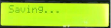
After the parameter setting is complete, press the QUIT button to exit and save the parameters.
The device works automatically:
After
the device is powered on, the controller will judge the data
transmitted by the sensor for automatic control, including the following
situations:
SH: If the voltage in any direction detected by the
sunlight sensor is higher than V3, the device will enter the sunny day
auto-tracking state after a total of 10 seconds.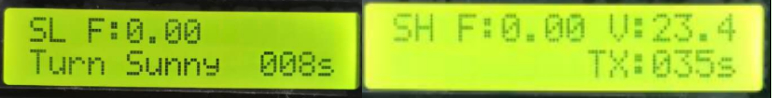
In
this state, the controller compares the voltage in the east and west
directions of sunlight sensor in order to control the platform. When
aligned with the sun, the device will enter the TX intermittent waiting
time. At the end of this time countdown, the controller re-compares the
voltage and the control platform for tracking.
SL: If the voltage
in any direction detected by the sunlight sensor is lower than V3, the
device will enter a cloudy or night state: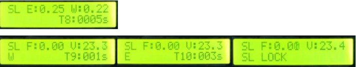
First,
it will enter T8 delay. During the T8 time, if the detected voltage is
higher than V3, the device will exit this state. If the time that
continues to be lower than V3 reaches the T8 time, the device will
perform the specified action, i.e., T9 time to the west and then T10
time to the east. In this state, the buzzer will sound at a certain
frequency to alert users.
After the action is executed, the device will enter the state of waiting for sunlight.
FS: When the wind speed detected by the wind speed sensor is higher than V2, the device will enter the wind speed homing state:
When
the signal voltage of the wind speed sensor is higher than the set V2
and lasts for 3 seconds, the device will judge that wind speed exceeds
the limit, and the controller will perform the wind speed homing action.
Its homing order is T3 time to the west, followed by T4 time to the
east. In this state, the buzzer will sound at a certain frequency to
alert the user.
After the homing is completed, the device will
enter T7 locking countdown. During the countdown time, if the voltage of
the wind speed sensor signal exceeds V2 again, T7 countdown will be
re-timed and locked. If it is cloudy at this time, the device will be
locked until sunlight returns.
In the above working state, the
parameters can be displayed alternately on the screen by pressing button
→/←. These parameters include: the voltage of sunlight sensor in the
east-west direction, the signal voltage of wind speed sensor, current
supply voltage, etc.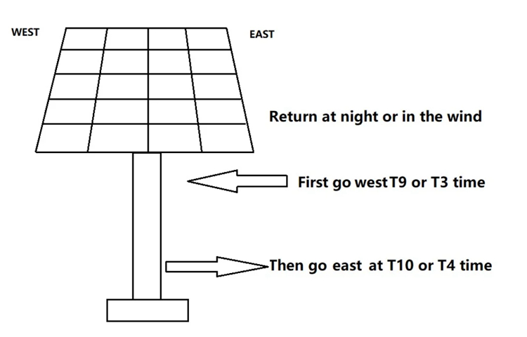
Meaning of Parameter Codes of LCD Screen:
AT: Automatic tracking. In this state, the device will automatically track the sun.
TX:
Waiting period entered after the east-west axis is aligned with the sun
in automatic tracking. During this period, the device will not operate.
E: East; W: West (indicates that the device moves in the corresponding direction)
V: Real-time voltage of power supply.
FS: When the wind speed exceeds the set value, the device will enter the flattening and homing state when encountering wind.
FS LOCK: The locked state after the wind speed is reset.
F: Real-time wind speed voltage in V.
SH: Automatic tracking in sunny days.
MT:
Manual operation status. In this state, buttons 1/2/3/4 of remote
control correspond to the manual movement of the north/south/west/east
direction.
SL: Weak sunshine. This means that the current controller
thinks that the sunlight is weak, that is, the device will go to sleep
and wait for the sunlight to appear again.
SL LOCK: Sleep state when there is weak sunshine.
T3:
The time (unit: seconds) for the device to drive westward when
performing the specified action of wind speed exceeding the limit. (Recommended setting value: the time taken by the platform from east to west * 1.2 times)
T4:
Performing the specified action of wind speed exceeding the limit, T4
is the time (unit: seconds) when the device is driven eastward after T3
time. (Recommended setting: The time it takes
for the platform to walk from west to east to the east-west axis posture
you want the platform to perform)
T7: After the device
performs the specified action of wind speed exceeding the limit, T7 is
self-locking time of the controller. The unit is seconds. The function
is to prevent the wind speed effect from being intermittent and causing
the device to perform frequent movements/tracking. During the
self-locking time, if the wind speed exceeds the limit value again, the
time will be immediately re-timed, so that the device will not operate
frequently. (Recommended setting: 600)
T8: Weak sunshine duration delay value (Recommended setting: 1800).
T9: The time (unit: second) it takes for the device to drive westward when performing a specified action with weak sunshine. (Recommended setting value: the time taken by the platform from east to west * 1.2 times)
T10:
When performing a specified action with weak sunshine, T10 is the time
(unit) for the device to be driven to the east after T9 time
(Recommended setting: The time it takes for the platform to walk from
west to east to the east-west axis posture you want the platform to
perform).
V1: Tracking accuracy setting. This value is the
voltage in the tracking accuracy range, that is, when the voltage
difference between the east and west detection silicon wafer is V, the
controller will believe that it is necessary to move the device or point
it at the sun. The smaller the value, the higher the accuracy.
Otherwise, the accuracy is lower. Please set it according to the
characteristics of the platform (recommended setting value: 0.05).
V2:
Wind speed start control voltage. When the voltage output by the wind
speed sensor is higher than V2, the controller thinks that it is
necessary to immediately specify the action to protect the platform (recommended
setting value: refer to the parameter correspondence table of the wind
speed sensor. The recommended setting value for the sensor configured by
our company is 0.12).
V3: Weak sunshine start control
voltage. This value is the threshold set by the controller for weak
sunshine. When none of the silicon wafer voltages in the two directions
of the sunlight sensor is higher than V3, the controller will think that
the current sunlight is weak and has no power generation value, and
cancel tracking. If sunlight does not return after T8 delay time, the
device will perform the specified action (recommended setting value: 2.0).
Our company reserves the right to change the hardware and software design of this controller without prior notice.
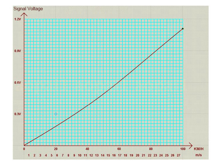
Parameter Table of Wind Speed Sensor (Wind Speed and Signal Voltage):