| Quantity | 3+ units | 10+ units | 30+ units | 50+ units | More |
|---|---|---|---|---|---|
| Price /Unit | $52.53 | $51.46 | $49.85 | $47.70 | Contact US |
 WT130A 1-300mm Professional Handheld Ultrasonic Thickness Gauge Metal/Glass Thickness Measurement Tool
$118.22
WT130A 1-300mm Professional Handheld Ultrasonic Thickness Gauge Metal/Glass Thickness Measurement Tool
$118.22
 WT100A 1-225mm Professional Handheld Ultrasonic Thickness Gauge Metal/Glass Thickness Measurement Tool
$79.35
WT100A 1-225mm Professional Handheld Ultrasonic Thickness Gauge Metal/Glass Thickness Measurement Tool
$79.35
 WT103 High Precision Digital Gauss Meter 5% Accuracy Multifunctional Backlight Tesla Meter Support mT/Gs Switch
$59.27
WT103 High Precision Digital Gauss Meter 5% Accuracy Multifunctional Backlight Tesla Meter Support mT/Gs Switch
$59.27
YF-BKT60V25A 25A 9-60V Automatic Buck Boost Module Buck Boost Converter Step up down Converter
Read before Purchasing:
- Do not use a regulated 3A/5A DC power supply as an input to test the power supply module.
- Basic technical knowledge and hands-on ability are highly recommended.
- Parameters such as under-voltage protection parameters are requested to be modified by users, and we can inform the modification method.
- Please have certain power supply test and measurement capabilities and equipment, do not take 3A adjustable regulated power supply used in labs to test the power supply. Figure out what kind of output you need, and then determine what kind of input parameters you need.
- Do not test the current-limiting power supply in CC mode of electronic loads.
- The output current regulation range means: if the input power is sufficient, output power supply is 20V, and a 0.4Ω resistor (adjusting CC potentiometer) is connected, the output current can only be adjusted in a range of 50A from a minimum to a maximum, and cannot be adjusted to the minimum limit value (except 0A).
Description:
DC-DC automatic buck-boost current can reach 25A, switching current can reach more than 33A, and it still works in a stable and reliable way. It is especially suitable for car batteries to charge lithium battery packs with high current, which is cost-effective.
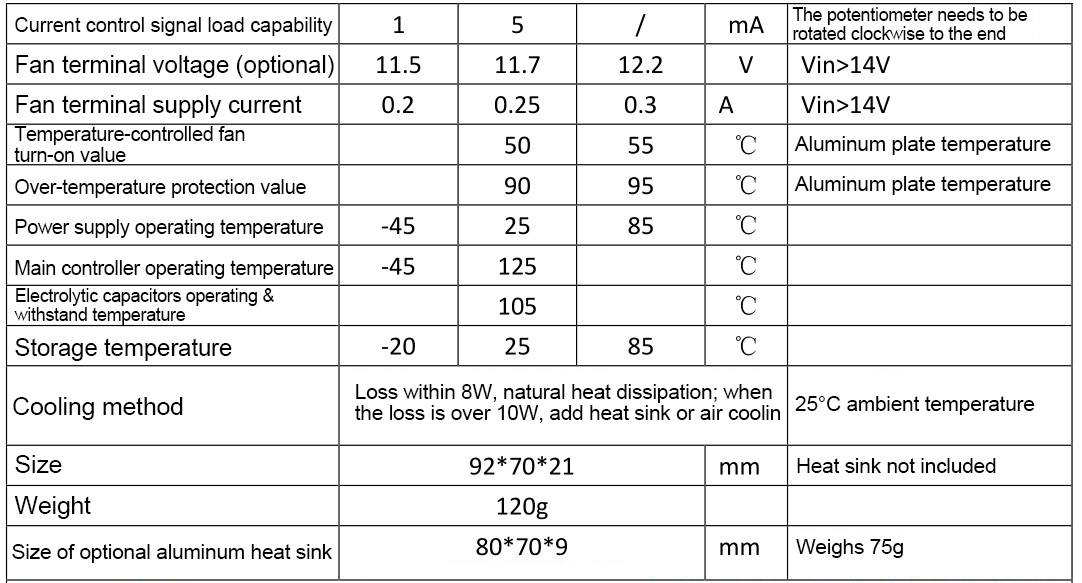
Our power supply design temperature is -45 to 105℃, the main controller temperature is -45 to 125℃, and the nominal temperature is -20 to 90℃. In our tests, it can still be started and work at -55℃.
Application:
- Regulated power supply can be adjusted to charge battery
- Input and output voltage are always applied
- Battery to charge the battery and for high-power LED
- A regulated power supply supplies power to devices
- Extend applications for external control voltage and current
Package Included:
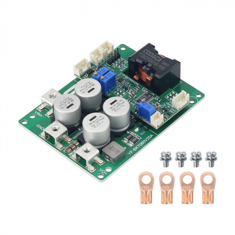
- 1 x Buck Boost Module
Note:
- Batteries are not included.
Instructions for Use:
Typical Performance (YF-BKT60V25A):
- Non-isolated four-switch synchronous buck-boost
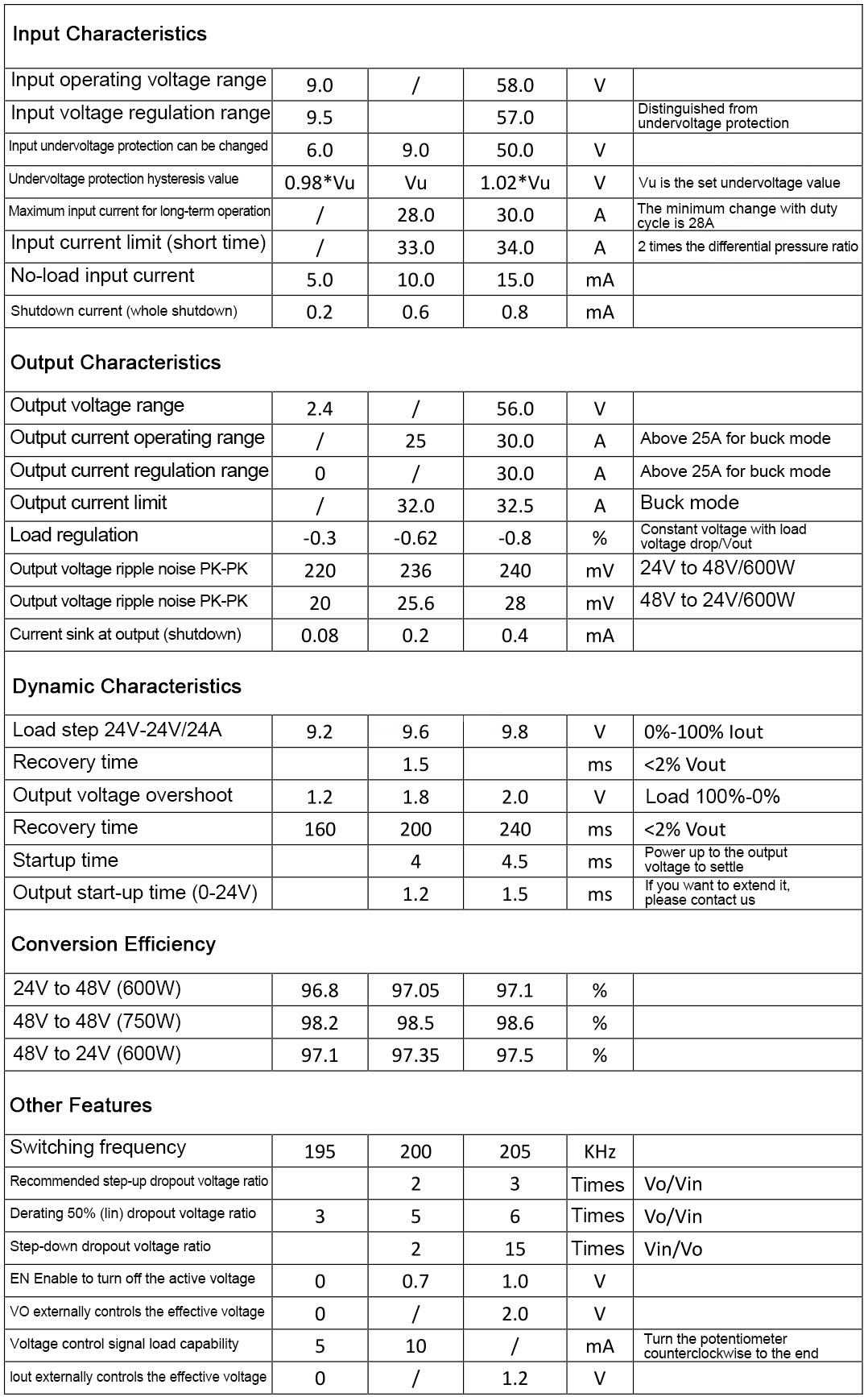
- Wide input DC9-58V; output DC3-56V
- Peak efficiency > 98.0%
- Over-current protection and short-circuit protection self-recovery
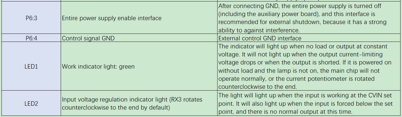
- Remote ON/OFF
- Over-temperature protection
- Optional temperature-controlled fan
- Constant current indicator light
- Input voltage is adjustable and suitable for battery panel fuel cells
- Output voltage and current are adjustable
- Output voltage and current are externally controllable
- Maximum inductor current of 30A
- Battery charge back-charge protection up to 60V
- Low quiescent current, high regulation accuracy, constant frequency operation MEI for easy prediction (Low EMI spread spectrum modulation mode is optional)
- Power: over 500W (input and output >24V)
- All test data is measured at 24V input voltage, pure resistive load, and room temperature at 25°C, no special specifying. Parameters are subject to change without notice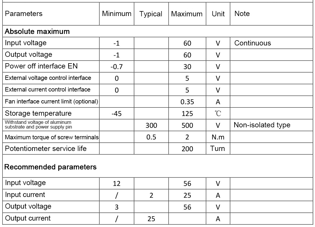
Attention:
1: Please calculate whether the maximum load is suitable according to lout=VIN*Iin*(0.92-0.98)/Vout. The parameter range needs to be within the values of the table, lin (max) = 28A can be suitable for all parameters. For example, Vin=12V, Vout=24V, and lout=13A. Vin=48V, Vout=24V, lout can be used above 25A.
2. The ripple current of the step-up output capacitor is large, the ripple current of the step-down input capacitor is large, and electrolytic capacitor can be connected in parallel to reduce the heating of the capacitor and extend the life.
3. It can be directly connected to battery to charge. It is recommended that the output voltage be adjusted correctly before connecting the target battery.
4. The slow start time is the same as the EN enable control delay time, and the output slow start time needs to be adjusted when the input source starts for a long time. For example, the AC adaptation output full load voltage settling time is 50ms, and the power supply start time is 2ms, which may cause AC to fail to start normally with load.
5. The input voltage regulation function cannot be limited to the case where the output current is 0, and the minimum limit output current is 2-5A, that is, a battery board will be offset when the power is low, and it cannot be adjusted beyond the range.
6. There are dynamic response requirements that can be specially optimized, such as output connection to sensitive equipment such as host computer.
7. Some parameters may be adjusted for different applications.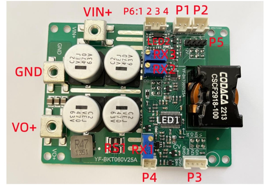
Attention:
1. When testing this power supply, it must be ensured that the input source can provide a large enough current (>33A) to ensure that the power supply does not collapse or even be damaged, especially when starting with load.
2. The start time of the input source must be less than the start time of this power supply (such as when the adapter is used as input), otherwise it may not be possible to start with load.
3. The input wire connected to this power supply shall not be too long (the internal resistance of the wire shall not be too large), otherwise the power supply may produce oscillation and abnormality.
4. If there is a diode in series with the input source to the power supply, the power supply may be damaged due to the surge voltage caused by the instantaneous switching on and off (line BOOST effect).
5. Do not use the cc mode of the electronic load as the load of this power supply, it is recommended to use the CR mode. This is because CC mode draws current, the power supply limits current, and the constant current state will cause the power supply to crash.
6. It is recommended to adjust the output voltage with a small current resistance load (dummy load) to ensure the real-time adjustment of the output voltage potentiometer, otherwise the output voltage changes slowly and the adjustment value is inaccurate.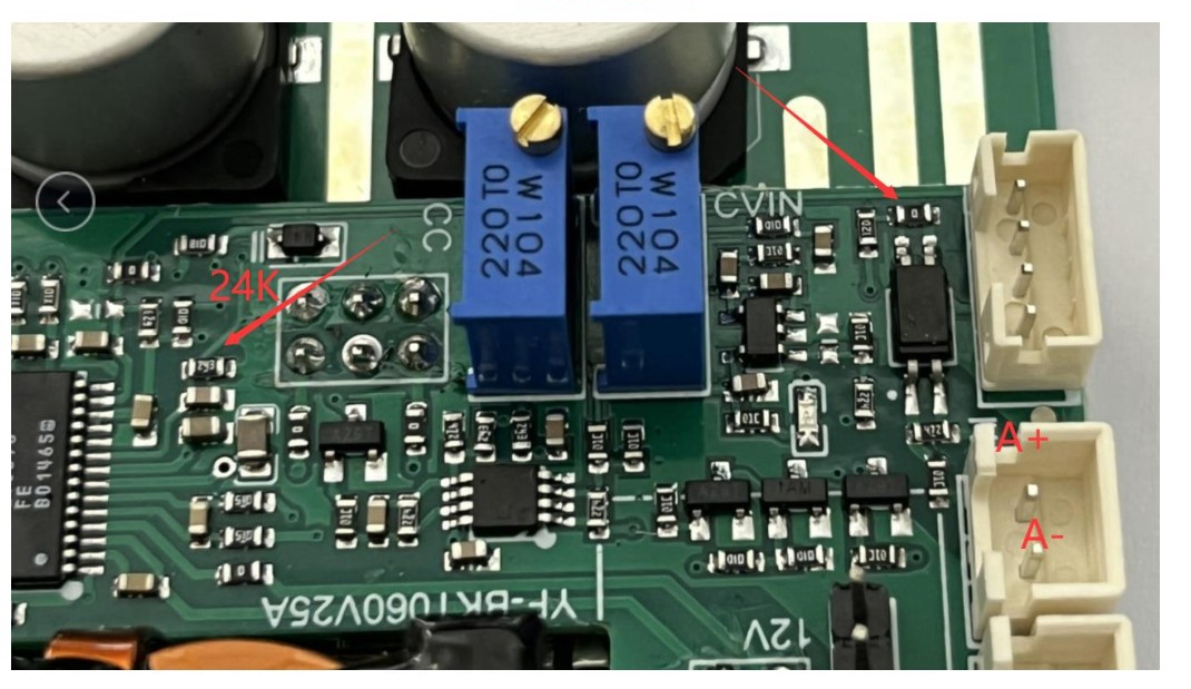
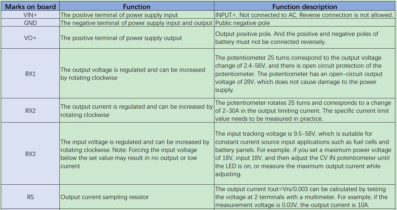
Modification method of undervoltage protection value: the left red arrow resistor defaults to 24K, then the undervoltage protection V=(130K/24K+1)*1.2V=7.7V (5% hysteresis range up and down).
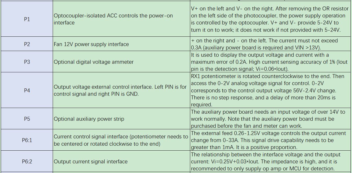
ACC control modification method ( provide 12-24V to boot; 12-24V is not provided and it will not boot): Remove the upper OR resistor, A+ and A- access voltages to get optocoupler to control power on/off. If the ACC function is used, it will not work once it is powered on and only ACC can make it worked.
Temperature test diagram. You can refer to the following test data for thermal design:
- Test parameters: input 48.25V and output 25.2V/20.31A, efficiency 98.0%, and loss power 10.4W.
- Test environment: The power board is exposed in a natural convection environment and placed vertically.
- Test time: about 30min, temperature basically no fluctuation.
- As can be seen from the pictures below, the ambient temperature is about 27°C, the highest point temperature near the inductor is 85.0°C, and the temperature at other locations is about 81°C. The maximum temperature on the front of the power board is about 90°C for the inductor coil, and 65-80°C for other locations. It can be known that the maximum temperature rise is 63 °C, excluding the inductor temperature rise of 55-60 °C.
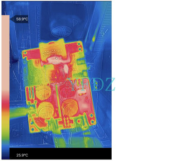
Thermal design reference example:
The actual parameters are input 20-28V and output 24V/20A. The efficiency can be roughly estimated to be 97-98%. The remaining margin is calculated according to 97%, and the power loss is 14.4W. If the ambient temperature is up to 30 °C, it may exceed the maximum use temperature, and it is necessary to cooperate with heat sink to strengthen the heat dissipation. If the ambient temperature is high, in a closed environment and the use of excessive power, a larger heat sink or fan can be configured for cooling.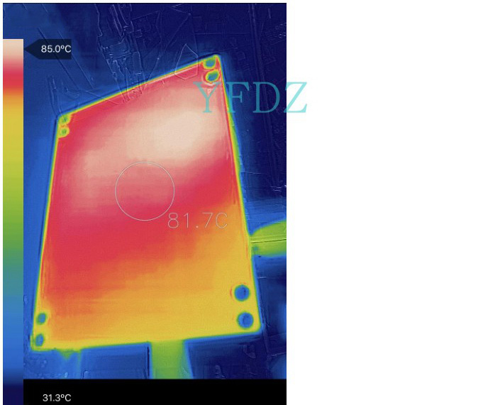
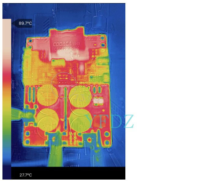
Below are heat dissipation temperature pictures. The test parameters are input 47.6V, output 48.5V/22.57A, power 1.1KW, loss 27.7W, and a 12V/0.21A fan (AFB0512HHD) 20mm away from the power supply. After working for a long time, the maximum temperature is only about 60 °C, and the maximum temperature rise is 35 °C. The actual use of adding a heat sink and adding a little air cooling can be applied to the situation where it is the maximum power of the power supply and the loss is up to 30W.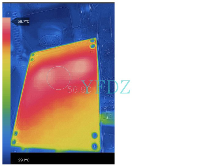
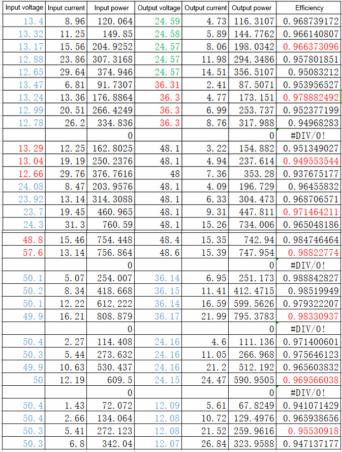
The efficiency test is recorded as follows, and other parameters can be roughly estimated.