| Quantity | 3+ units | 10+ units | 30+ units | 50+ units | More |
|---|---|---|---|---|---|
| Price /Unit | $11.76 | $11.52 | $11.16 | $10.68 | Contact US |
 High Precision 17-340Nm Torque Tester Digital Display Torque Meter Support Peak/Track Mode Switch
$33.33
High Precision 17-340Nm Torque Tester Digital Display Torque Meter Support Peak/Track Mode Switch
$33.33
 High Precision 10-200Nm Torque Tester Digital Display Torque Meter Support Peak/Track Mode Switch
$30.22
High Precision 10-200Nm Torque Tester Digital Display Torque Meter Support Peak/Track Mode Switch
$30.22
 High Precision 1.5-30Nm Torque Tester Digital Display Torque Meter Support Peak/Track Mode Switch
$30.22
High Precision 1.5-30Nm Torque Tester Digital Display Torque Meter Support Peak/Track Mode Switch
$30.22
YLF-BT-0082 LCD Voltage Meter Voltmeter Ammeter Display w/ RS485 Port For 10A 30V MODBUS Protocol
Link for PC Software and Protocol Description:
http://pan.baidu.com/s/1eSC3BDS
Attention:
- Professional knowledge is highly recommended.
- After receiving the goods, please read and understand the wiring method and then power on and test it before soldering. 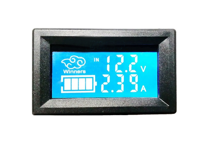
Version Introduction:
With
RS485 communication interface, it is the version for MODBUS. It can use
the host computer software to collect data, and also communicate with
PLC, DCS, smart meters and other equipment!
Calibration Instructions:
The
meter has a calibration function, so there is no need to worry about
inaccurate measurement display. If you find that the display is not
accurate, you can use the following method to calibrate. After receiving
the product, it is recommended to perform a calibration according to
the following method.
Calibration Method:
First use a
multimeter to measure the precise value of measured voltage, then
connect the measured voltage to our meter head, press two buttons at the
same time to enter calibration mode. Adjust -Button and + Button to
make the displayed voltage the same as the voltage measured by the
multimeter. For example, if the multimeter measures 12.65V, adjust the
displayed voltage to 12.65V by pressing the buttons. After three
seconds, it will automatically save and exit.
Measurement Instructions:
Please
read carefully! Measured voltage can be set to independent power supply
and non-independent power supply modes. There is a black jumper cap on
the module, plug it in to indicate non-independent power supply, and
unplug it to indicate independent power supply. Wiring methods of these
two ways are different, please read wiring diagrams clearly before
using! Do not connect wrong wires, or the voltmeter may burn out.
Non-independent power supply means that the supply voltage of the module
is the measured voltage (5-30V). Independent power supply means that
the module power supply and the measured voltage are separated. At this
time, the module power supply voltage is 5-24V, and the maximum measured
voltage is the purchased voltage value (standard 30V is 0-30V, 100V is
0-100V).
Note: The 10A 100V version can only use independent power supply connection!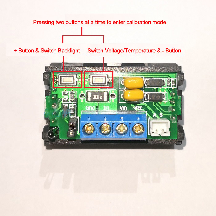
Specifications:
- Can measure voltage, current and ambient temperature at the same time
- Voltage range: 0-30V
- Current range: 0-10A (please strengthen heat dissipation when the temperature of large current exceeds 60℃)
- Temperature range: -10 to 100℃ (accuracy 1%)
- Accuracy: 1% (±1 digit, the larger the voltage and current range, the lower the accuracy)
- Support for standard Modbus RTU protocol, communication way RS485
- Voltage and temperature are switched to display (Voltage and temperature can be switched through the button on the back)
- With protocol function, 1 to 255 device addresses can be set by the upper computer software;
- Product size: 47.8*28.8*30MM
- Installation opening: 45*25.5MM
- Weight: 24G
Package Included:
- 1 x Voltmeter Ammeter For 10A 30V MODBUS
Interface Description:
- Terminals A and B are marked as RS485 interface, used for Modbus communication.
-
GND is voltage -. IIN measures the negative pole of current load. VCC
is the positive pole of power supply under test when it is not
independently powered, and the positive pole of module power supply when
it is independently powered. When VIN is independently powered, it is
the positive electrode of the voltage to be measured and the positive
electrode of the load.
Wiring Diagram For Measuring Voltage and Current:

Test Instructions For Modbus:
1. Connect Hardware:
- Connect RS485 serial port, A connects A, B connects B, connect the measured voltage.
2. Software Settings:
- Set serial port number in "Communication Settings" and open the serial port.
-
Set the module address in "Analog acquisition" item (The default
address is "1". If you don't know the module address, you can change the
module address in the "Module Address Change" item)
- Click "Acquisition" command in "Analog acquisition".
- If a "communication error" occurs, confirm whether the A and B terminals of RS485 interface are reversely connected.


 Microprocess Panel Controller Meter")


")