| Quantity | 3+ units | 10+ units | 30+ units | 50+ units | More |
|---|---|---|---|---|---|
| Price /Unit | $571.88 | $560.21 | $542.70 | $519.36 | Contact US |
 30MHz Opensource DIY Current Probe AC/DC High Frequency Magnetic Field Probe with 5A and 10A Magnetic Heads
$83.37
30MHz Opensource DIY Current Probe AC/DC High Frequency Magnetic Field Probe with 5A and 10A Magnetic Heads
$83.37
 VG820 HDMI-compatible2.0 Signal Generator Built-in 50+ Kinds of Test Pattern Signal Analyzer with 7-inch Touch Screen
$884.37
VG820 HDMI-compatible2.0 Signal Generator Built-in 50+ Kinds of Test Pattern Signal Analyzer with 7-inch Touch Screen
$884.37
 WT220-40 40CH Data Logger Multi-Channel Data Analyzer High-Speed Version with 7" Touch Screen
$3,319.13
WT220-40 40CH Data Logger Multi-Channel Data Analyzer High-Speed Version with 7" Touch Screen
$3,319.13
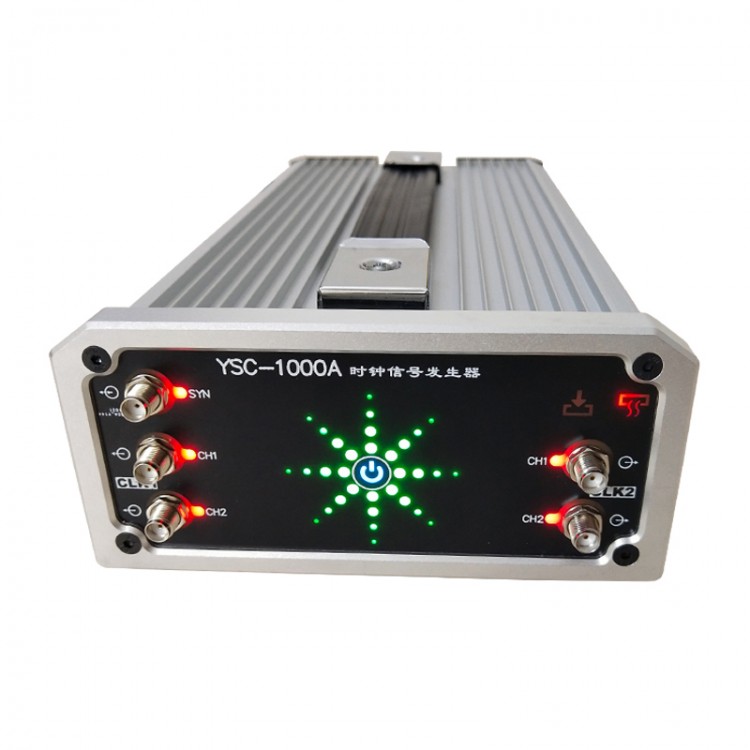
YSC-1000A 2MHz to 3GHz Clock Generator Signal Generator Frequency Generator Four-Channel Low Noise
Description:
The frequency output range of the YSC-1000A clock signal generator is 2MHz to 3GHz, with 4 channels. At the same time, it has low phase noise and excellent spurious rejection. Its highly stable OCXO reference provides high frequency accuracy and stability specifications. An external reference clock signal can also be introduced.
YSC-1000A adopts personalized touch switch, and its control is more personalized. The control interface is a serial port for convenient communication. Complete software development protocols are provided to facilitate secondary development.
Advantages:
- Wide frequency band
- High frequency accuracy
- Low phase noise
- High spurious rejection
- Strong scalability
Package Included:
- 1 x Clock Generator
Introduction of Control Interface:
The partition design is adopted to meet the user's operating habits, and the function settings are presented in the form of a system block diagram, making the operation more intuitive.
With offline storage/recall function, the system configuration can be saved and recalled after power-on. It is convenient for field testing.
Main Indicator Test:
1. Output Power and Flatness
Test scenario: Set the clock source to [Internal Clock] mode, enable four port outputs, configure the output frequencies of CLK1 and CLK2 respectively, and test the output power and flatness of the signal.
① CLK2-CH1 port
② CLK2-CH2 port
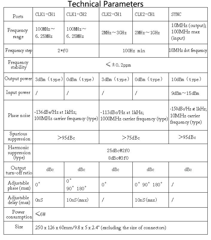
2. Output Phase Noise
Test scenario: The clock source is set to [Internal Clock] mode, four port outputs are enabled, and the output frequencies of CLK1 and CLK2 are configured respectively to test the phase noise of the output signal of the corresponding port.
①CLK1-CH1 port
100MHz output phase noise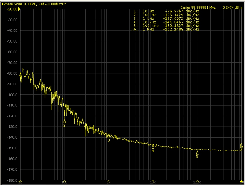
② CLK1-CH2 port
100MHz output phase noise
③ CLK2-CH1 port
3GHz signal output phase noise
④ CLK2-CH2 port
1GHz signal output phase noise
⑤ SYNC port
10MHz output phase noise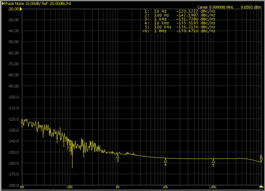
3. Harmonic Suppression
Test scenario: Set the clock source to [Internal Clock] mode, enable four port outputs, configure the output frequencies of CLK1 and CLK2 respectively, and test the harmonic suppression of the output signal of the corresponding port.
① CLK1-CH1 port
100MHz output harmonic suppression
② CLK1-CH2 port
100MHz output harmonic suppression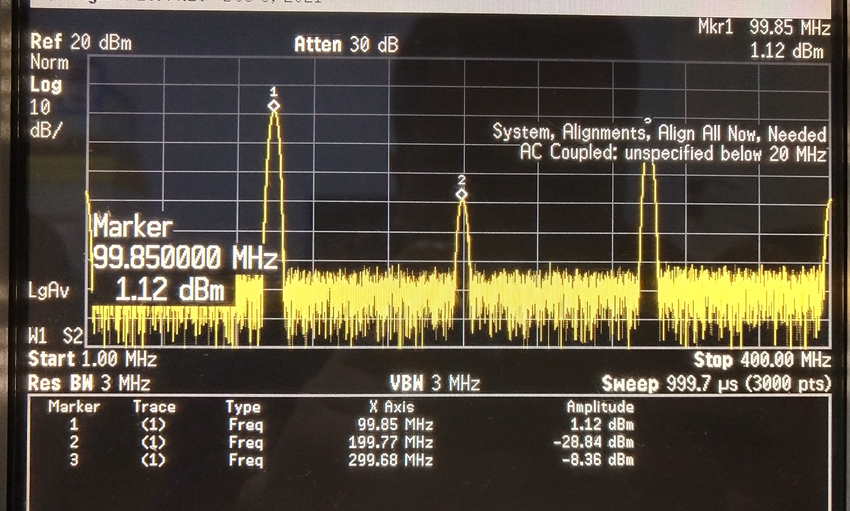
③ CLK2-CH1 port
3GHz output harmonic suppression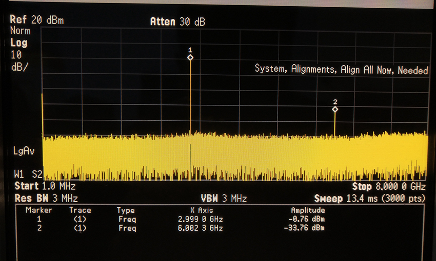
④ CLK2-CH2 port
100MHz output harmonic suppression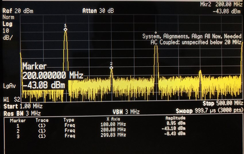
⑤ SYNC port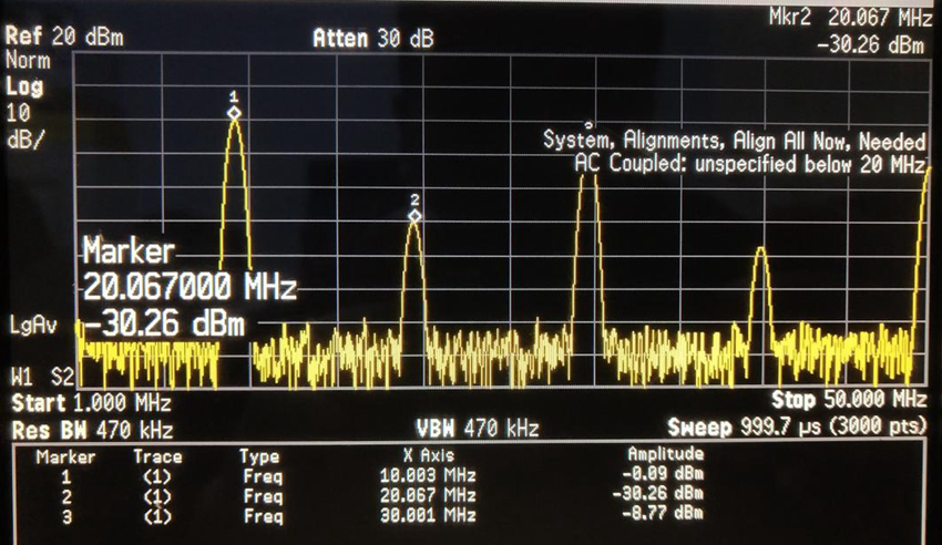
4. Spurious Suppression
Test scenario: The clock source is set to [Internal Clock] mode, four port outputs are enabled, and the output frequencies of CLK1 and CLK2 are configured respectively to test the output signal spurious rejection ratio of the corresponding port.
1GHz output harmonic suppression
5. Output Signal Phase Delay
Test scenario: Set the clock source to [Internal Clock] mode, configure the output frequencies of CLK1 and CLK2 respectively, enable four port outputs, and test the phase delay of CH1 and corresponding CH2 signals.
① CLK2 outputs 100MHz, the phase delay is set to 0, and the time delay is set to 0. CH1 port (yellow curve) and CH2 port (blue curve) waveform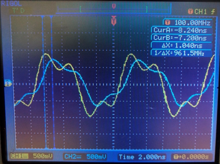
② CLK2 outputs 100MHz, the phase delay is set to 90°, and the time delay is set to 0. CH1 port (yellow curve) and CH2 port (blue curve) waveform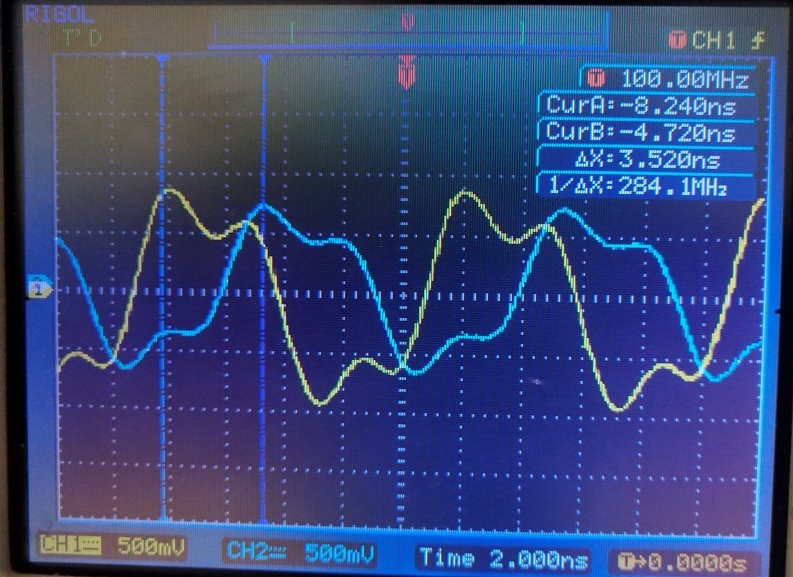
③ CLK2 outputs 100MHz, the phase delay is set to 180°, and the time delay is set to 0. CH1 port (yellow curve) and CH2 port (blue curve) waveform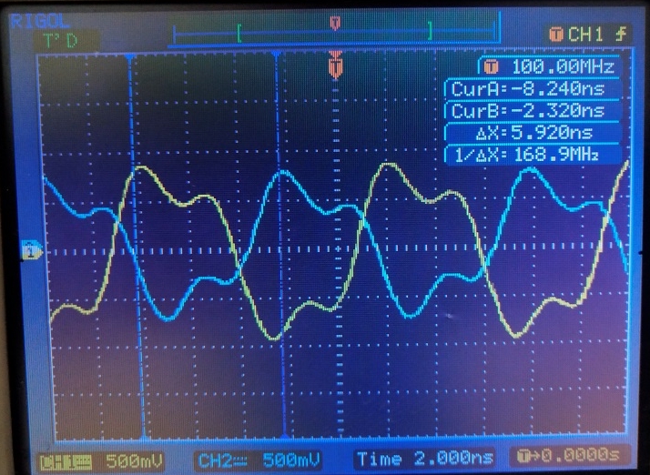
6. Output Signal Phase Delay
Test scenario: Set the clock source to [Internal Clock] mode, configure the output frequencies of CLK1 and CLK2 respectively, enable four port outputs, and test the time delay of CH1 and corresponding CH2 signals.
① CLK2 outputs 10MHz, the phase delay is set to 0°, and the time delay is set to 0nS. CH1 port (yellow curve) and CH2 port (blue curve) waveform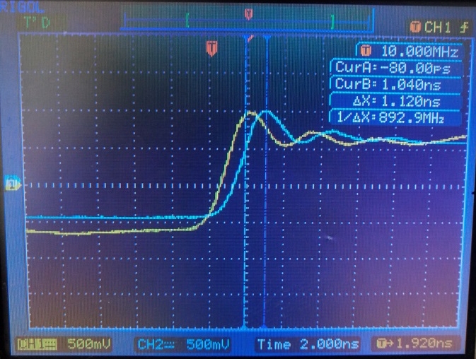
② CLK2 outputs 10MHz, the phase delay is set to 0°, and the time delay is set to 1.5nS. CH1 port (yellow curve) and CH2 port (blue curve) waveform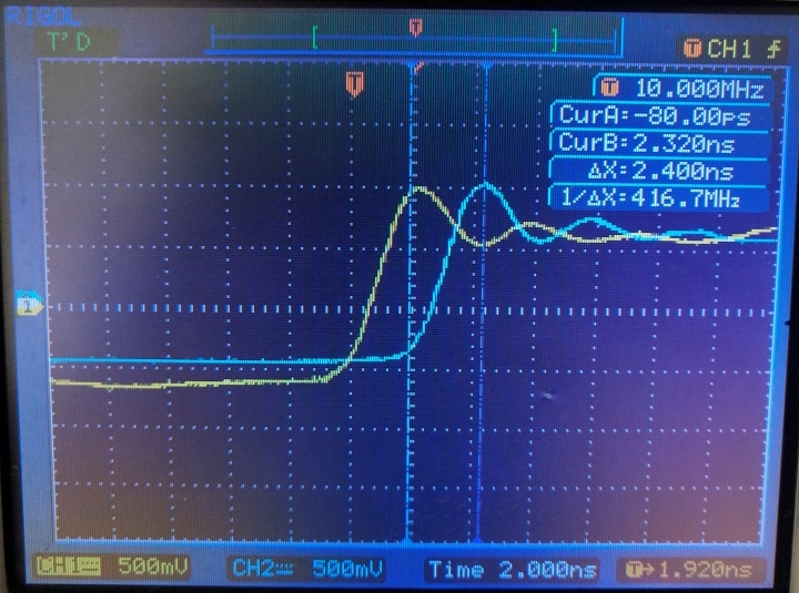
③ CLK2 outputs 10MHz, the phase delay is set to 0°, and the time delay is set to 5nS. CH1 port (yellow curve) and CH2 port (blue curve) waveform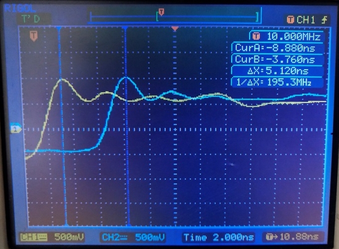
④ CLK2 outputs 10MHz, the phase delay is set to 0°, and the time delay is set to 10nS. CH1 port (yellow curve) and CH2 port (blue curve) waveform