1-3KHZ to 0-10V PWM Signal to Voltage Converter Digital-Analog PLC
Main Parameters:
- Input: DC 12~30V
- Input current: no less than 100mA.
Note:
- After power-up, when there is no input signal, the output is 0V. There is output only when there is input.
Function:
- PWM converts digital signals into analog signal ( 0 to 10V). Can be used for industrial control panel PLC or other signal interface switching.
Use:
- PWM signal input frequency range: 1KHZ-3KHZ.
- PWM signal input level range:
- 4.5V to 10V peak to peak level, jumper inserted at 5V. This type signal mainly for conventional industrial control card (such as MACH3 board), for 5V the CPU interface.
- 12 to 24V peak to peak level, jumper inserted at 24V. This type signal mainly for conventional PLC interface
0-10V analog output details:
- When the signal input port is not connected, the output port gives 10V. The first time when we power on this module, we better calibrate it: find a 50% duty ratio signal, connect to DIN-, DIN+, the amplitude matches corresponding jumper. When frequency is at 1kHz ~ 3kHz, use a multi-meter to test AO, GND. The meter should be showing around 5V. We adjust the potentiometer on the converter module to make multi-meter shows 5V sharp. After this is done, we have calibrated and matched pulse signal with this converter module. The module has a definition of 0.1V. Output current 10mA. If duty ratio is in opposite to voltage, we can select or un-select PWM output pin STEP LOW / ACTIVE in MACH3 software.
- Power Input Range: 12V-30V (Power requirements: more than 100MA
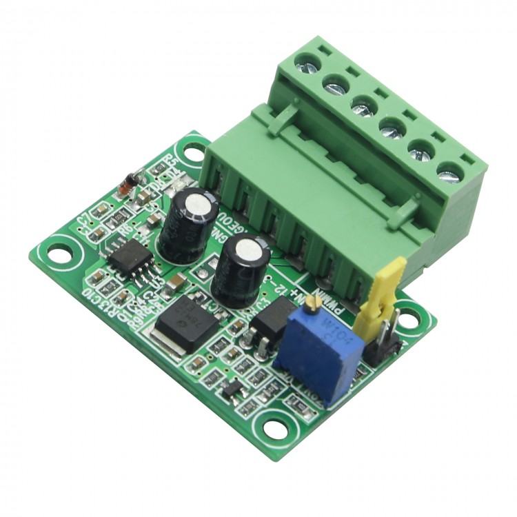
Definitions about markings onboard:
DIN+: PWM signal input positive terminal. (When common negative connection, this port connects to PWM Signal. When common positive connection, this port connects to 5V or 24V)
DIN-: PWM signal input negative terminal. (When common negative connection, this port connects to GND of signal. When common positive connection, this port connects to PWM signal)
- 12-30V: power input positive terminal
GND: power supply ground
AO: Analog 0-10V output port
GND: signal ground. It is through to GND of power input.
Other Features:
- power supply with anti-false-connection protection
- with power indicator LED onboard
- by adjusting potentiometer board, can match the calibration of different frequency PWM signal pulses
 SZGH-CNC-IO-12 IO Relay Board with 12 Relays for CNC Lathe Milling Controller and CNC Controllers
$117.57
SZGH-CNC-IO-12 IO Relay Board with 12 Relays for CNC Lathe Milling Controller and CNC Controllers
$117.57
 NEWKER NEW990TDCa-2 2 Axis CNC Controller English Version + 5M/16.4FT Cable for CNC Lathe Grinder
$605.02
NEWKER NEW990TDCa-2 2 Axis CNC Controller English Version + 5M/16.4FT Cable for CNC Lathe Grinder
$605.02
 MP21-10-2 Universal Wired Tool Setter Normally Close Engraving Machine Tool Setter CNC Processing Tool Set
$44.70
MP21-10-2 Universal Wired Tool Setter Normally Close Engraving Machine Tool Setter CNC Processing Tool Set
$44.70