| Quantity | 3+ units | 10+ units | 30+ units | 50+ units | More |
|---|---|---|---|---|---|
| Price /Unit | $132.03 | $129.33 | $125.29 | $119.90 | Contact US |
 FUZRR ES3000P Multifunctional Micro-controller 3-Wire Ground Resistance Tester 0-20Kohms High Precision Earth Resistance Tester
$275.47
FUZRR ES3000P Multifunctional Micro-controller 3-Wire Ground Resistance Tester 0-20Kohms High Precision Earth Resistance Tester
$275.47
 150W Multifunctional Bluetooth Battery Capacity Tester CC/CR/CP/CV/PT/BRT Intelligent DC Programmable Electronic Load
$59.21
150W Multifunctional Bluetooth Battery Capacity Tester CC/CR/CP/CV/PT/BRT Intelligent DC Programmable Electronic Load
$59.21
 FUZRR ES3090E 220A Loop Resistance Tester Micro-ohmmeter for High Voltage Switch Contact Resistance Measurement
$1,466.23
FUZRR ES3090E 220A Loop Resistance Tester Micro-ohmmeter for High Voltage Switch Contact Resistance Measurement
$1,466.23
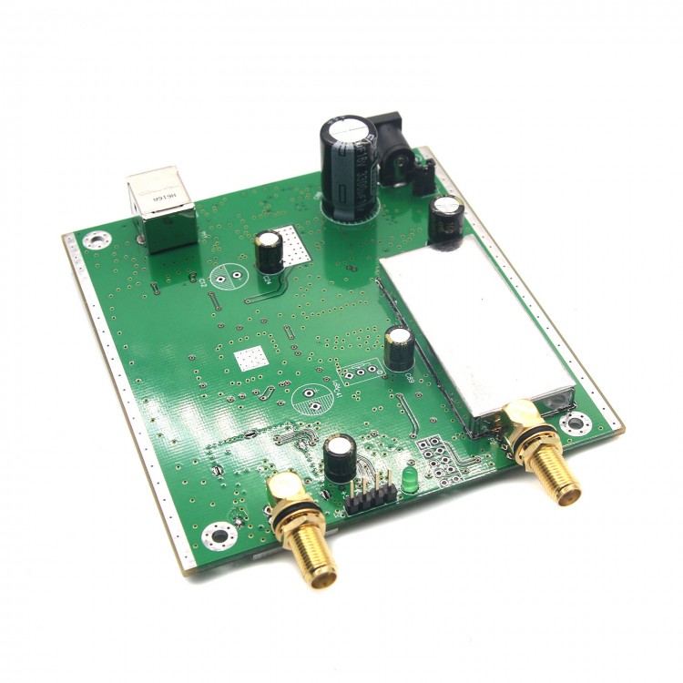
0.05MHz-550MHz USB Sweep Frequency Generator Sweeper Simple Frequency Characteristic Tester NWT500
Download Manual Here:
http://pan.baidu.com/s/1slOUma5
Specifications:
- Item Name: NWT500 Sweep analyzer, Amplitude-Frequency Characteristic Analyzer
- Frequency Range: 0.05-550MHz
- Stepping: 1Hz
- Output Signal Strength: 3dBm
- Logarithmic Dynamic range: Better than 50db
- Linear Detection Range: 0-1V EMF
- Interfaces: USB, SMA
- Power Supply: DC11.5-12.5V / 0.5 A
- Control Software: WINNWT4 V4.08.02
- PCB Size: 117*93*30mm
- Features: supports logarithmic, linear detection, liner and LOG support DC input. with 0-50DB attenuator, enabling impedance, VSWR (impedance standing wave needs to be used with bridge) and other functions measurement
- 4-layer design
Package Included:
- 1 x Sweep Frequency Generator
Note: Other accessories are not included in the package.
FAQ:
- Q1: What is sweep frequency generator? What's it for?
- A1: The frequency sweeper is also called frequency characteristic tester, which can measure the frequency and amplitude characteristics of tested parts. For example, measuring an LC resonant circuit, the amplitude vs. frequency curve, to understand the frequency characteristics of the LC back.
- Q2: What is the difference between the NWT series frequency sweeper and the BT3 frequency scanner using a picture tube?
- A2: The NWT series is a digital frequency sweeper, with small step intervals, and connected to a computer to process data, which can be used as VFO output. Smaller, lighter, and more accurate than older frequency sweepers. In particular, NWT4000-1 and NWT4000-2 can be used as a simple spectrum.
- Q3: Why does the scanner not respond when connected to a computer?
- A3: You need to check whether the USB driver is installed, whether the external DC power is connected correctly, and whether the software settings are correct.
- Q4: Can the scanner measure a duplexer and how to measure it?
- A4: It can be measured that the duplexer is actually two filters. The output of the frequency sweeper is connected to the antenna end and the receiving end of the duplexer, and the input of the frequency sweeper is connected to the machine end to measure.
- Q5: How to use it to test antenna?
- A5: You can use standing wave bridge or tee to measure antenna. Standing Wave Bridge Measurement Method: The standing wave ratio can be measured with a bridge, which can be measured qualitatively. Please note that the frequency sweeper is only suitable for standing wave bridges with RF output, and cannot be used with bridge with detection output. Tee Measurement Method: Measurements can also be made with a tee instead of a standing wave bridge. However, only comparative measurements can be made, not qualitative.
- Q6: What are the precautions for using the frequency sweeper?
- A6: Since it needs to be connected to a computer and tested device, please pay attention to whether grounding is good, and the detection terminal cannot input too high level, otherwise the detection element will be damaged.
- Q7: What to do if the USB port has insufficient power?
- A7: The power supply current in the USB2.0 protocol is 0.5A, which is sufficient for the device. If there is insufficient power supply, please check whether the USB cable is in good contact, or replace the cable with a better one, or use it with a USB3.0 interface (power supply current 0.9A), or connect a USB hub with an external power supply and sufficient power.
- Q8: The impedance of the instrument and the device under test do not match. What will happen and how to solve it?
- A8: The impedance of the device does not match, and the power cannot be transmitted at 100%. When there is reflection, the measurement parameters (gain, fluctuation, insertion loss and bandwidth) will be incorrect. You can add a transformer or resistor to perform impedance matching before measuring.
- Q9: How can I improve the input and output impedance accuracy of the instrument?
- A9: Attenuators can be added to the input and output of the instrument. The value of the attenuator is generally 3DB. If you want it to be more accurate, you can change it to 10DB or higher value attenuator, the disadvantage is that it will lose dynamics.