| Quantity | 3+ units | 10+ units | 30+ units | 50+ units | More |
|---|---|---|---|---|---|
| Price /Unit | $54.65 | $53.54 | $51.87 | $49.64 | Contact US |
1-1000MHz 1GHz RF SWR Reflection Bridge RF Directional Bridge For RF Network Measurement AYT-1
Description:
The electric bridge is a sensor for measuring the reflection coefficient, which is used for radio frequency network measurement. Output reflected signal has amplitude and phase information, and features wide frequency and high directivity. The simple application of this bridge can be combined with a radio frequency spectrum analyzer or a frequency sweeper with a tracking source, which can measure the return loss of the device and the reflection of the entire frequency band. For example, a vector voltmeter or a vector voltage measurement device plus a signal source can be accurately measured Circuit vector impedance, complete the test and debugging of the RF matching circuit. Widely used in antenna measurement and debugging, radio frequency circuit and radio, television and communication equipment measurement and debugging.
The directivity of this bridge is ≥35dB in the whole section, ≥40dB in the middle and low frequency.
Specifications:
- Model: AYT-1
- Frequency range: 1MHz-1GHz (1-1000MHz)
- Characteristic impedance: 50Ω
- Directionality: ≥35dB
- Maximum input power: ≤0.2W
- Insertion loss: 6.5dB±0.5dB (from input end to measurement end)
- Connector type: input terminal, output terminal and measuring terminal are all N Female
- Product Size: 95 x 65 x 32 mm (LxWxH)
Package Included:
- 1 x Set of Reflection Bridge
Note:
- Three N-head bridges are sent by default. If the version with SMA test ports is needed, please contact us. Thank you!
- Other items pictured are not included in the package.
General Use of Reflection Bridge:
1. Reflective Bridge Directional Self-calibration:
1.1 Output the tracking signal source of the reflection electric bridge to the spectrum analyzer. The frequency range of the spectrum analyzer is set to 1~1000MHz, the level is 100MHz per division, and the output amplitude of the tracking signal source is 0dBm (others are also possible, the following are measured at 0dBm output).
1.2 The DUT end of the reflective bridge (device end under test) is open. (Nothing is connected, the frequency is low, and the requirements are not high. This can be the case; the frequency is high, the requirements are high, and the opener must be connected, because there is a test end face (position reference), the outer conductor capacitance when the inner core is opened... etc., cannot N Simple open circuit), 1GHz signal is not high, we simply open the N block. Note the spectrum analyzer amplitude. As shown in figure -14dBm.
1.3 Self-calibration of Reflection Bridge:
The DUT is terminated with a 50 ohm precision load to see how much the amplitude measured by the spectrum analyzer has dropped. The bigger the better. Below 1GHz, a drop of 35dB is considered acceptable, and 40dB is considered excellent. 30dB is a fault. When the frequency is several GHz, it can also be used around 30dB. When the frequency is several GHz, it is not easy to reach 30dB. The amplitude drop can be understood in this way. If the 50 ohm precision load and the corresponding 50 ohm (etc.) in the reflective bridge are perfectly ideal, then the reflective bridge is completely balanced and there is no output, that is, the amplitude drop is infinite, of course this is impossible. As shown in the figure, two precision loads are connected to the spectrum analyzer, and both amplitudes are below -50dBm, which is greater than 36dB, (-14-(-50)=36), that is, the directivity of the reflective bridge is better than 36dB. The directional self-calibration result is qualified.
Another 50 ohm Precision Load Loaded Self-calibration Result: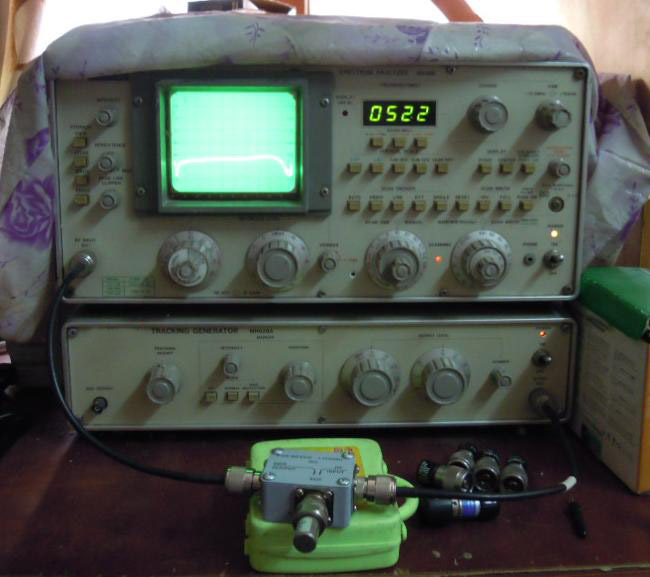
If there is no 50 ohm precision load or the load accuracy is not enough, this step of self-calibration can be completely omitted.
2. Measure the return loss of device under test (return loss, reflection coefficient, standing wave ratio can be calculated mutually, one can count the other two) If the over return loss is 20dB, then the reflection coefficient is 0.1, the standing wave ratio is 1.22, use the formula , Software, charts can be more convenient for mutual calculation.
2.1 Measure the actual antenna parameters. As shown in the figure, the antenna under test is a 432MHz small antenna.
1~1000MHz
20MHz Per Grid
It can be seen that at the center frequency, the antenna return loss is about 20dB (about two divisions, each vertical 10dB), that is, the reflection coefficient is 0.1, the standing wave ratio is 1.22; the antenna return loss is 10dB (reflection coefficient 0.32, standing wave ratio 1.92) The bandwidth is about 20MHz (two half grids), that is, the bandwidth at which 10% of the power is reflected is 20MHz.
2.2 Measuring A Device:
Connect the blue label device as shown in the figure, the amplitude is about -34dBm, that is, the return loss is about 20dB.
What device? As shown in the figure, it is a 10dB (frequency up to 12.4GHz) attenuator.
The return loss is 20dB, which is twice that of 10dB. Fortunately, this understanding can be figured out. The signal passes from the DUT end of the bridge through the 10dB attenuator to the open circuit (the other end of the attenuator is not connected). What is an open circuit. The open circuit is S11. 1. The open circuit is the total reflection back, and the reflected signal at the open circuit returns to the DUT terminal of the bridge through the 10dB attenuator, which attenuates a total of 20dB. This is not actually the meaning of Return Loss (Return Loss).
2.3 The measured return loss of the blue 10dB attenuator when it is open is 20dB. I see, what else can I do? The return loss is 20dB, the corresponding reflection coefficient is 0.1, the reflection coefficient
Γ=(Z-Zo)/(Z+Zo), 0.1=(Z-50)/(Z+50), Z solution is 61.1 ohms, look at the figure and use a multimeter to measure the attenuator resistance, 61.9 ohms, the contrast error is not To 1 Euro. Originally, a spectrum analyzer (with a tracking signal source or an external signal source, or a high-frequency millivoltmeter plus a signal source) plus a reflection bridge can also measure "impedance" (scalar impedance). (The actual measured impedance is the impedance on the Smith circle with a reflection coefficient of 0.1. The attenuator can work up to 12 GHz. The influence of reactance is ignored, and the influence of reactance is not considered. The intersection of the 0.1 circle and the real axis impedance has one of two points It is 61.1 ohms). If you have a vector voltmeter, you can measure the vector impedance, that is, the network analyzer measures S11.


