| Quantity | 3+ units | 10+ units | 30+ units | 50+ units | More |
|---|---|---|---|---|---|
| Price /Unit | $21.87 | $21.43 | $20.76 | $19.86 | Contact US |
12V/24V 12A DC Motor Driver Board Dual Motor Driver H Bridge WSDC2412D V3.0 For DC Brushed Motors
Features:
- Small size 50 x 50 x 12.5mm/2 x 2 x 0.5"
- Multiple protections, built-in over-voltage, undervoltage, and overheating protection circuits
- Control signals are fully isolated. Compatible with 3-5V input
- High power. Can drive 2pcs 300W motors at the same time
- High-speed PWM isolation input, minimum pulse width 3us, and isolation bandwidth 10MHz
- Supports full duty cycle input.Can be separated from the MCU to achieve direct control of external switches, and limit switches can be connected in series
- Operating voltage 6.5-29V. Support 7-24V DC brushed motors
- Each channel has a two-color indicator to indicate the direction of rotation of motors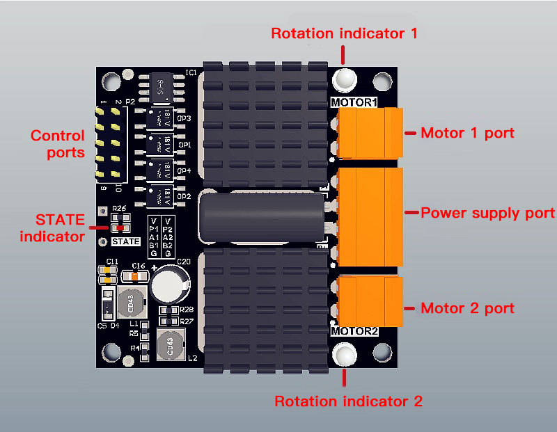
Description:
Dual DC brushed motor driver is specially designed to drive low-voltage DC motors. It uses high-performance MOSFETs to form an H-bridge drive. It can continuously output 12A current per channel and can drive a DC motor with a maximum of 300W electrical power. The timing of the components in the driver is highly optimized, allowing the minimum pulse width of the PWM input to be as low as 3us, fully ensuring the dynamic adjustment range of the PWM, and improving the control of the motor. The on-board protection circuit reduces the possibility of driver damage under abnormal working conditions. The protection status is output in real time by the indicator light. The all-optical isolation input enhances the safety of the main control MCU circuit, and can significantly improve the electromagnetic compatibility of the system.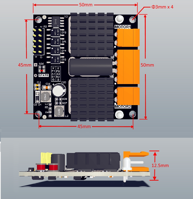
Working Parameters:
- Power supply voltage VP: minimum 6.5V; maximum 28V
- Overvoltage protection value: 28.5V typical
- Undervoltage protection value: 6.3V typical
- Power supply current IP: maximum 24A (two-terminal wiring)
- Single channel continuous output current Imc: maximum 12A (VP=24V resistive load)
- Single channel peak output current Imp: Maximum 70A (VP=24V; t=100ms)
- Single channel peak output current Imp: Maximum 200A (VP=24V; t=10us)
- Logic input voltage Vin: minimum 3V; maximum 5.5V (same as logic signal amplitude)
- Logic input current Iin: typical value 15mA (VCC=5V)
- PWM input frequency: typical value 18kHz; maximum value 60kHz
- PWM minimum pulse width: 2uS typical (positive and negative pulse)
- Overheating protection: minimum 85℃; maximum 95℃ (location of sensor)
- Working temperature: minimum -25℃ ; maximum 85℃
Package Included:
- 1 x Set of DC Motor Driver Board
Attention:
1. Except for special instructions, the driver tests are all carried out at 20℃ in an open environment.
2. Two terminals are P+ and P- terminals, each of which is connected with two power cords (due to the limitation of the terminal capacity).
3. The PWM input frequency is recommended to be higher than 10kHz. When it is lower than this value, there may be obvious current noise. The mute application is set at around 17-18kHz.
Running Logic: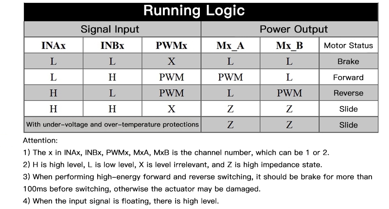
Indicator Light:
- STATE: Steady on: Normal operation. Fast flashing: Power supply is over-voltage and the output is turned off. Slow flashing: The power supply is undervoltage and the output is turned off. Double flashing: The driver is overheated and the output is off.
- LM1: Motor 1 direction indicator. Green means forward rotation; red means reverse rotation
- LM2: Motor 2 direction indicator. Green means forward rotation; red means reverse rotation
Typical Application: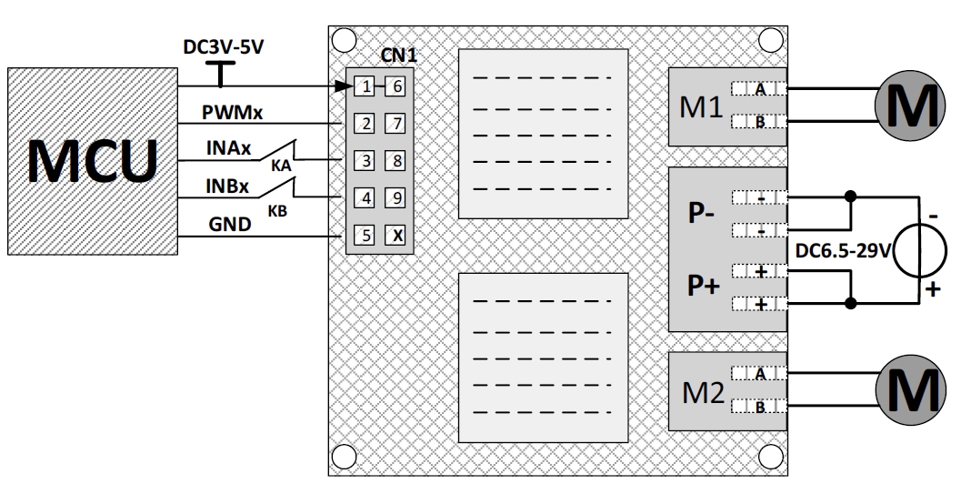
MCU controls the operation of motors, adding limit switch function (KA, KB are limit normally closed contacts):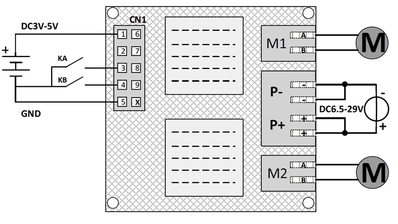
Buttons (KA, KB) control the forward and reverse rotation of motors without the involvement of MCU
Control Input Ports:
Pin 1: VCC. Isolated positive power supply input. Compatible with 3.3V and 5V power supplies
Pin 2: PWM1. M1 channel duty cycle modulation input, high-speed isolation, and bandwidth 50MHz
Pin 3: INA1. M1 channel control logic input A
Pin 4: INB1. M1 channel control logic input B
Pin 5: GND. Isolated power supply ground input
Pin 6: VCC. Isolated positive power supply input. Compatible with 3.3V and 5V power supplies
Pin 7: PWM2. M2 channel duty cycle modulation input, high-speed isolation, and bandwidth 50MHz
Pin 8: INA2. M2 channel control logic input A
Pin 9: INB2. M2 channel control logic input B
Pin 10: GND. Isolated power ground input
Attention:
1. When the input signal is floating, there is high level.
2. The control input terminal CN1 has a 2.54mm pitch 2x5 double row of pin headers.
Drive module includes a motor and a power supply terminal plugs. The following figure shows the effect after the terminal plugs areinserted. The wiring method is the terminal plug screw to tighten the wire.
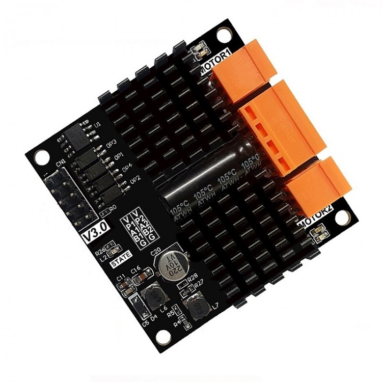


")


