| Quantity | 3+ units | 10+ units | 30+ units | 50+ units | More |
|---|---|---|---|---|---|
| Price /Unit | $69.31 | $67.89 | $65.77 | $62.94 | Contact US |
 G1009 10-inch Embedded HD Industrial Monitor 1024x768 Hook Mount TFT Display with BNC/VGA/AV/HDMI-compatible Ports
$109.57
G1009 10-inch Embedded HD Industrial Monitor 1024x768 Hook Mount TFT Display with BNC/VGA/AV/HDMI-compatible Ports
$109.57
 G121SN01 V3 Color Active Matrix LCD Display Panel Designed for Various Industrial Applications
$88.42
G121SN01 V3 Color Active Matrix LCD Display Panel Designed for Various Industrial Applications
$88.42
 RTU-307D NET-07D 8AI-8DI-8DO Data Acquisition Module IO Module (RS485+RS232) for Industrial Use
$76.89
RTU-307D NET-07D 8AI-8DI-8DO Data Acquisition Module IO Module (RS485+RS232) for Industrial Use
$76.89
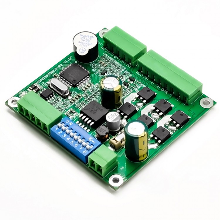
12V/24V/36V 180W BLDC Motor Driver Board Brushless DC Motor Driver Board AQMD3605BLS-B2 w/ 35W Motor
Advantages:
- Speed, current, and position three-loop control
- Speed regulation, steady speed, precise and rapid positioning
- Automatic flow reduction and stall protection for overload and stall
- Ordinary brushless can also be used as stepping servo control
- Potentiometer, pulse and 485 control
Functional Characteristics:
- Support voltage 9V-36V, maximum output current 7A, and rated output current 5A
- Support potentiometer and switch, analog signal and logic level, PWM/frequency/pulse signal, and RS485 input signals
- Support duty cycle speed regulation (voltage regulation), speed closed loop control (steady speed), position closed loop control (step/servo), and torque control (steady current) speed regulation
- Support acceleration/deceleration buffer time and acceleration/deceleration acceleration control, which can automatically accelerate/decelerate and accurately position within the specified stroke
- Support single potentiometer, double potentiometer independent, double potentiometer comparison control forward and reverse speed
- Support analog signal voltage range configuration and logic level voltage configuration. Analog signal supports a voltage range of 0~3.3V. Logic level can support voltages such as 0~24V. Support analog signal linearity adjustment and logic level threshold configuration
- Support external PWM and frequency signals to adjust motor speed. Support external pulse signal for stepping control of motors
- Support for MODBUS-RTU communication protocol. Support the use of 485 to perform hybrid control of the duty cycle, steady speed, and position speed regulation of motors
- Motor current PID adjustment control, the maximum start/load current and braking current can be configured separately. Support motor overload current limit and locked-rotor shutdown
- Support external limit switch and locked-rotor limit
- Support motor phase sequence learning, with fault alarm
- 18KHz PWM frequency, motor speed regulation without PWM scream
- For ARM Cortex-M3 at 72MHz processor
- Support temperature measurement, current limit or shutdown when overheating
Parameters of Compatible Motors:
- Motor with rated voltage of 36V: suitable for motors with rated power of 120W and below or rated current below 5A to work at full capacity for a long time;
- Motor with rated voltage of 24V: suitable for motors with rated power of 80W or less or rated current of less than 5A to work at full capacity for a long time;
- Motor with rated voltage of 12V: suitable for motors with rated power of 30W and below or rated current of less than 5A to work at full capacity for a long time.
Attention:
This driver has a long-term rated current of 5A and a maximum output current of 7A (tens of seconds). The rated power marked on a motor generally refers to output power. Considering the work loss of a motor, the motor efficiency should be considered when calculating the rated current. Rated current = rated power/rated voltage/efficiency.
Applications:
Suitable for automatic control, including robotic arms, access gates, automatic doors, service robots, rail PTZ, electric drawers and smart cars.
Special Features:
1. Hall self-learning. The three-phase line and three-Hall signal line of the motor can be connected to the driver out of order. The working mode of the driver is changed to motor learning by setting the DIP switch of the driver. After turning on the power supply of the driver, the Hall sequence of a motor can be learned automatically. The learning is completed after 6 commutation control of the motor, and the motor can be driven normally.
2. Steady speed control response time.
- Test conditions: Motor 24V 60W, diameter 5.7CM/2.2", number of poles 4, commutation 12 times per revolution, no load.
- Parameter configuration: Speed PID parameters are configured to 0.2, 0.01, 0.01 in turn. Position PID is configured to 30, 0.01, 0.01, and acceleration and deceleration acceleration are configured to 6500Hz/s.
- Test result: When speed stabilization algorithm selects speed closed-loop control, the motor is switched from forward rotation 3000RPM (corresponding to a commutation frequency of 600Hz) to reverse 3000RPM, the use time is about 1.0s, there is no overshoot, and the motor forward and reverse switching process is smooth. When the speed stabilization algorithm selects time-position closed-loop control, the motor is switched from forward rotation 3000RPM to reverse rotation 3000RPM, the use time is about 0.5s, the overshoot is 1.5%, and the motor forward and reverse switching process is smooth.
3. Very low speed and steady speed control. Time-position closed-loop control speed stabilization algorithm can be used to control motors at very low speed (such as below 60RPM). The steady speed control of motors is uniform, without sudden speed and slowness, and the minimum can be controlled to 1RPM.
Note: In the case of extremely low-number steady-speed control, the position PID parameters should be configured smaller, such as 10, 0.01, and 0.01 in sequence.
4. Automatic acceleration and deceleration control for reciprocating motion. During reciprocating motion control, the driver can learn the total stroke of reciprocating motion in advance (the value can also be directly configured). According to the configured acceleration and deceleration acceleration and maximum speed, it automatically controls the motor to move to the target position quickly and smoothly in accordance with Newton's law of motion.
5. Motors can be adjusted at any position within a fixed stroke. The driver can learn the total stroke of the reciprocating motion in advance (you can also directly configure the value) before using the potentiometer, analog or PWM to adjust the position of the motor within a fixed stroke. The position of the motor and the input are in a linear relationship. If the potentiometer is turned to the midpoint and the input duty cycle is set to 50%, the motor will move to the midpoint of the stroke.
6. Brushless motors can also be controlled step by step. Select input signal as PWM/frequency/pulse, configure the pulse type as pulse, and configure the working mode as position control. Then, like a stepper motor operating a brushless motor, one pulse signal can be used to control the rotation angle of the motor, and the other pulse signal can control the direction of rotation. The rotation angle of the motor corresponding to each pulse can be configured.
7. Brushless motors can also be servo controlled. In 485 communication control mode, the target position (absolute position or relative to the current position) can be directly given to make the driver rotate to the target position. According to the set acceleration and deceleration acceleration and maximum speed, the driver automatically controls motors, and the motors quickly and smoothly move to the target position according to Newton's law of motion. During the movement, the driver can predict the remaining time required to complete the task.
Electrical Parameters:
- Power supply input voltage: DC 9V~36V
- Rated output current: 5A
- Maximum output current: 7A
- Hall sensor interface voltage: 5V
- Maximum soft braking current: 3A
- Number of output channels: single
- Potentiometer resistance: 10K~50K
- Input signal port accepts voltage range: -0.5V to 25V (except for failure/complete signal output ports)
- Analog signal range: any within the range of 0~3.3V
- Digital signal voltage range: any within the range of 0~24V, LvTTL, TTL, HvTTL, etc.
- PWM input signal support frequency range: 100Hz~10kHz (output PWM frequency is fixed at 18kHz)
- Frequency input signal support range: 0~10kHz
- Output PWM frequency: 18kHz
- Output PWM resolution: 1/1000
- RS485 communication parameter range: baud rate 9600~115200bps, data bit 8, support odd number, even number, no parity. Check bit and stop bit total 2 digits
- Support for Modbus: Support for Modbus-RTU, support 03H, 06H, 10H function code. Configurable slave address range 1~128, support broadcast
- Current detection resolution: 0.04A
- Steady flow control accuracy: 0.1A
- Duty cycle speed adjustment range: 0~100.0%
- Steady speed control adjustment range: -3276.8 to 3276.7Hz
- Position control adjustment range: -2147483648 to 2147483647
- Torque control adjustment range: 0~7A
- Limit control: support; two limit switches can be connected externally or limit when locked
- Soft start/soft brake: support; current limit start, brake and set acceleration/deceleration time and acceleration
- Over-current / locked-rotor protection: support; current limit output when over-current; shutdown when locked-rotor
- Reverse connection protection of power supply: support
- Output short circuit protection: configurable
- Braking action time: soft braking usually 0.1s~0.3s
- Working temperature of motherboard: -25℃ to 85℃
- Dimensions: 7.0 x 6.5 x 2.1cm/2.8 x 2.6 x 0.8"
Package Included:
- 1 x Set of DC Motor Driver
Note:
- This drive is suitable for DC brushless motors with inductance.
Principle:
This driver uses leading motor current precision detection technology, sensorless brushless motor self-test speed, sensorless brushless motor rotation position detection, regenerative current constant current braking (or brake) technology and powerful PID adjustment technology. It can perfectly control the smooth forward and reverse rotation, commutation and braking of motors, real-time regulation of output current to prevent overcurrent, and precise control of motor speed and rotation position. The response time of motors is short and the recoil force is small.
- Motor acceleration and deceleration control: a soft start mode with automatic current adjustment and automatic acceleration control. Motors can start quickly and smoothly with low recoil force. Support acceleration/deceleration time and acceleration/deceleration acceleration configuration.
- Motor brake control: Energy consumption braking mode with automatic current adjustment. Motor braking time is short without strong shock and vibration. Support brake current configuration.
- Motor commutation control: The process of switching between forward and reverse rotation of motors is controlled internally by the drive. It automatically controls deceleration, soft braking and soft start. No matter how frequently the commutation signal changes, it will not cause damage to the driver or motors.
- Motor steady speed control: detect the speed and rotation position through the Hall signal.Use PID adjustment algorithm for closed-loop control. Support speed closed-loop control and time-position closed-loop control.
- Motor position control: detect the rotation position through Hall signal. Use PID adjustment algorithm for position closed-loop control, and use brake resistor for deceleration.
- Motor torque control: Realize the control of motor torque by adjusting the size of the output current.
- Motor overload and locked-rotor protection: When motors areoverloaded, the driver will limit the current output to effectively protect motors; when motors are locked, the driver can detect the state and brake the motors.
- Internal interference suppression: The drive circuit and the control circuit are coupled through interference consumption and transient interference suppression, which ensures that the control circuit is not affected by the interference of the driver circuit.
- External interference suppression: ESD protection devices and electrostatic discharge circuits are used to protect all interfaces from ESD. This makes the internal circuit work stably and protects the internal components from being damaged by the transient high-voltage static electricity applied to the interface.
- 485 communication interference suppression: Use signal and power isolation chips to isolate the 485 transceiver circuit to suppress interference.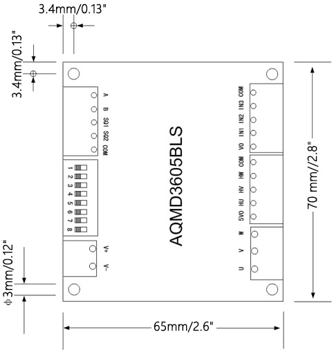
The size of the driver is 70 x65 x 21mm/2.8 x 2.6 x 0.8". The diameter of the mounting hole is 3mm/0.12", and the distance from the center of the mounting hole to the side is 3.4mm/0.13".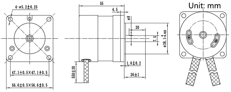
Motor AK57BL55-230-035:
- Rated voltage: 24V
- Rated torque: 0.11Nm
- Rated speed: 3000RPM
- Rated power: 35W
- Rated current: 2.4A
- Number of poles: 4
- No-load speed: 4200RPM
- No-load current: 0.3A