| Quantity | 3+ units | 10+ units | 30+ units | 50+ units | More |
|---|---|---|---|---|---|
| Price /Unit | $35.51 | $34.78 | $33.69 | $32.24 | Contact US |
 SpyVerter R2 Upconverter Based on Switched Double Balanced Mixer for Airspy Mini HackRF One RTL-SDR
$71.45
SpyVerter R2 Upconverter Based on Switched Double Balanced Mixer for Airspy Mini HackRF One RTL-SDR
$71.45
 SURECOM SW-33PLUS 100W 125-525MHz SWR Power Meter Mini VHF UHF PWR SWR Meter 50Ω Impedance (US Plug)
$49.02
SURECOM SW-33PLUS 100W 125-525MHz SWR Power Meter Mini VHF UHF PWR SWR Meter 50Ω Impedance (US Plug)
$49.02
 SURECOM SW-33PLUS 100W 125-525MHz SWR Power Meter Mini VHF UHF PWR SWR Meter 50Ω Impedance (EU Plug)
$49.02
SURECOM SW-33PLUS 100W 125-525MHz SWR Power Meter Mini VHF UHF PWR SWR Meter 50Ω Impedance (EU Plug)
$49.02
2-Band AM FM Signal Generator Radio Signal Generator Wireless Transmitter for Electronics Enthusiast
Description:
The signal generator is a small device that can generate and emit electromagnetic waves. It is mainly used to repair and tune radios. Its main function is to emit electromagnetic waves of different frequencies for radio to receive, which is convenient for radio debugging.
The FM range is about 76-108MHZ and and there is a separate 10.7MHz IF signal output. The AM medium-wave frequency range is 400kHz-1650kHz, including the intermediate frequency 465kHz.
There is a sine wave inside the device with an audio of about 800Hz-1100Hz. External audio signal is also supported. The adjustment system can be adjusted. It can transmit signals wirelessly and wired output is supported. There is a 3.5mm socket to output high-frequency signal and low-frequency signal. It can also be used as a signal injector, which is a practical tool for repairing, assembling and debugging radios.
The transmission distance of AM MF is about 2m/6.6ft. The transmission distance for FM band is about 10m/32.8ft. The above distances are for reference only.
Experimental AM FM Transmitter:
- This is an experimental small home wireless transmitter through which audio signals such as mobile phones can be transmitted and received with a regular radio. It can be connected to an external microphone and used as a small wireless microphone. The machine has four frequencies that can transmit. They are 90M, 105M, 12M and 1000KHz. You can select any of the frequencies to transmit. Transmission distance is 10-20m/32.8-65.6ft. It can be used as a reference for electronics enthusiasts to learn the knowledge of wireless transmission.
- It is only suitable for ordinary home indoor use, and should not interfere with others in public places.
Package Included:
- 1 x Signal Generator
Note:
- Battery is not included in the package.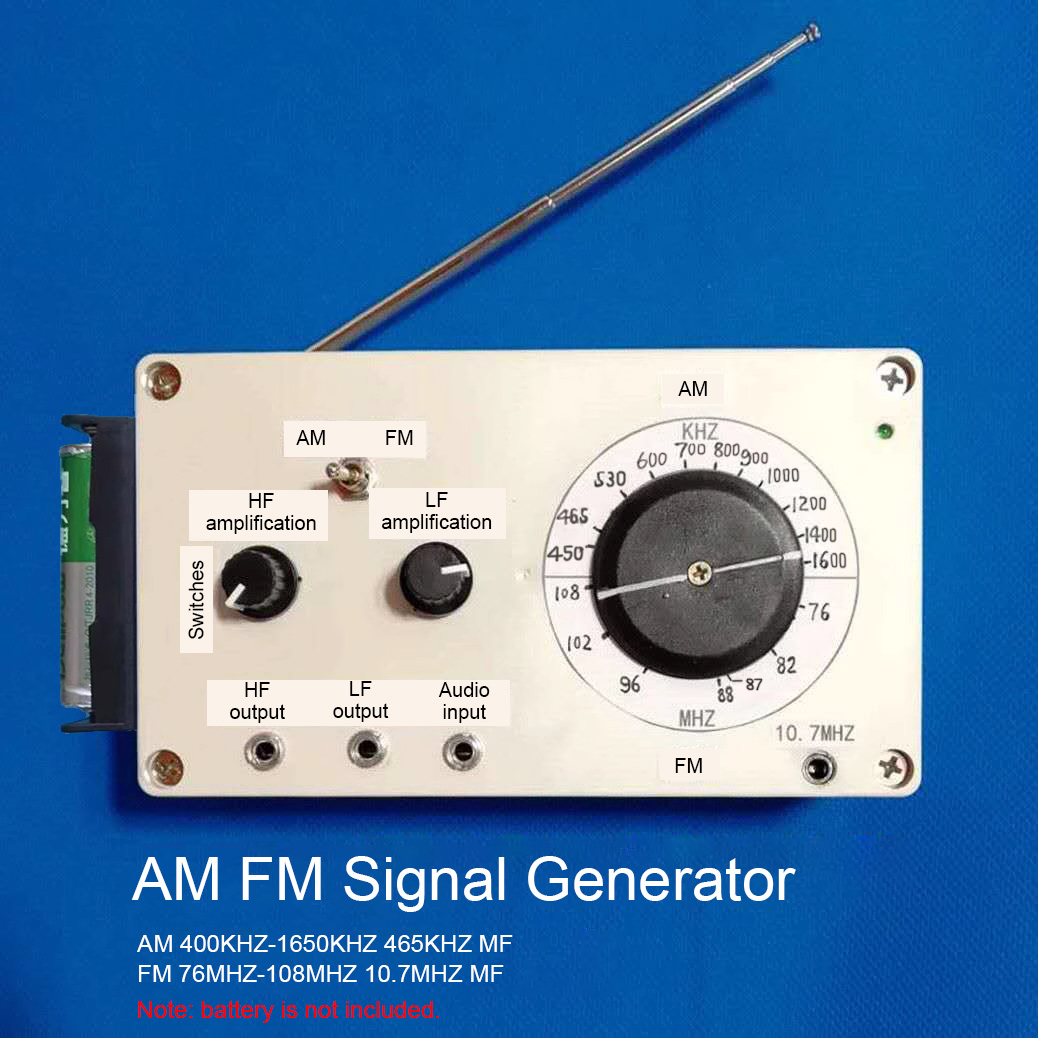
How to Use AM FM Signal Generator?
1. Connect it to a power cord. Toggle the power switch on the HF amplification knob, and the indicator light of the power supply will turn on, indicating that the power supply has been turned on.
2. Toggle the band switch to select bands. The bands are divided into AM and FM bands. When using the FM band, please pull out its telescopic antenna.
3. Rotate the frequency dial to an appropriate frequency. The upper part of the frequency dial is AM frequency, and the lower part is FM frequency. After selecting the band and adjusting to the desired frequency, let the radio also adjust to the corresponding band and frequency position to receive wirelessly. Adjust the LF amplification knob to change the modulation until the size of the received signal is appropriate.
4. The audio input port can input audio signal. Rotate the LF amplification knob to adjust input signal appropriately. Both FM and AM bands can receive signals.
5. The LF output port can be wired to output low-frequency signals. The low-frequency amplification knob adjusts the output signal size. When the band switch is in the FM position, the low-frequency output signal is large, and when the band switch is in the AM position, the low-frequency output signal is small.
The HF output socket can be wired to output amplitude-modulated high-frequency signal, and the HF amplification knob can adjust the output signal size. FM signal can only be transmitted and output wirelessly. The FM band can increase the antenna length and increase the transmission distance.
6.When 10.7MHz signal is output in the FM band, connect an output cable to radio medium frequency transformer, and listen to the sound while debugging the medium frequency transformer until the radio is muted, indicating that the medium frequency transformer has been adjusted to 10.7MHz.
465kHz IF Signal & Audio Signal Injection Method:
Dial the signal generator to the medium-wave band, and the dial points to the 465kHz position, and inject the IF signal into the mid-amplification and frequency conversion stages of the superheterodyne receiver. For silent faulty machines, you can see where the signal is not passing. For machines that have sound but want to adjust the MF frequency, you can adjust the MF transformer step by step. In addition, at this time, the signal generator has a signal radiated out, as long as the signal generator is close to the radio magnetic antenna, there can be an intermediate frequency signal in series into the frequency conversion level, and the sound with audio signal can be heard. Theoretically, radio can receive the IF signal in the entire frequency range, because the rejection of the IF signal by the antenna coil is limited, but the sound is smaller. It is possible to simply bring the signal generator close to the radio antenna and adjust the IF transformer step by step to get maximum sound.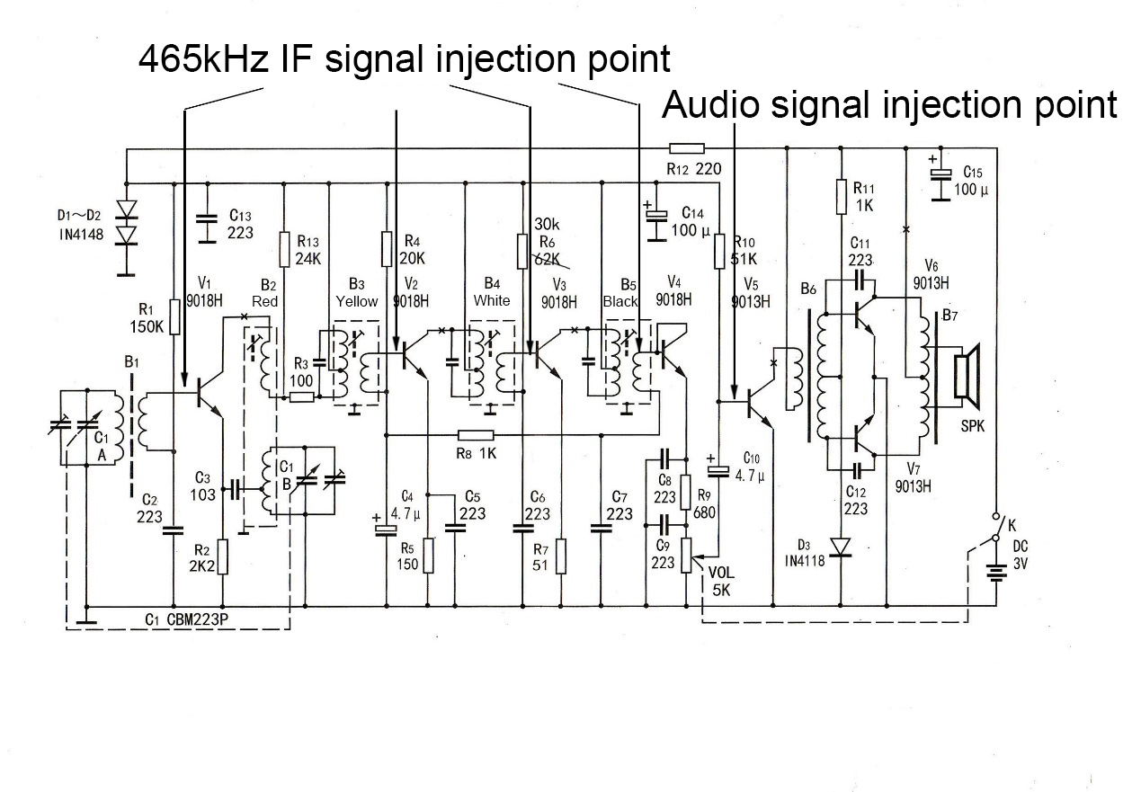
For radio LF amplification stage testing, you can output an audio signal from the signal generator's LF output. Connect this audio signal to the low-frequency amplification stage and check it one by one to find the fault point.
How to Use FM 10.7MHZ IF Signal Source?
The following is a debugging reference circuit.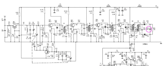
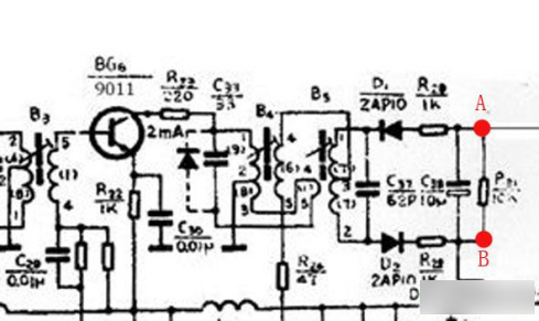
- Referring to the above circuit, the 10.7mhz intermediate frequency signal is injected from the base of the first intermediate frequency transformer BG2, and one end is grounded. Use a multimeter to monitor the voltage on the C29 A and B, that is, the output voltage.
- Adjust the magnetic core of the first IF transformer to make the voltage of points A and B reach the maximum;
- After adjusting the magnetic core of the second IF transformer to make the voltage of points A and B reach the maximum, adjust the magnetic core by 0.005mm in the direction of large inductance to broaden the low-end bandwidth of the IF transformer.
- After adjusting the magnetic core of the third IF transformer to make the voltage of points A and B reach the maximum, adjust the magnetic core by 0.005mm in the direction of small inductance to broaden the high-end bandwidth of the IF transformer.
- Adjust the magnetic core of the first intermediate frequency transformer to make the voltage of points A and B reach the highest;
- Adjust the magnetic core of the second intermediate frequency transformer to make the voltage of points A and B reach the highest and the sound is not distorted. You can also hear the sound to mute, which means that the intermediate frequency transformer has been adjusted. Different radio circuits are similar, please refer to this circuit.


