| Quantity | 3+ units | 10+ units | 30+ units | 50+ units | More |
|---|---|---|---|---|---|
| Price /Unit | $46.47 | $45.52 | $44.10 | $42.20 | Contact US |
 1PCS 3-Meter LC-LC Dual Core Multi-mode OM4 Optical Fiber Cable High Quality 10-Gigabit Optical Fiber Jumper
$30.38
1PCS 3-Meter LC-LC Dual Core Multi-mode OM4 Optical Fiber Cable High Quality 10-Gigabit Optical Fiber Jumper
$30.38
 1PCS 2-Meter LC-LC Dual Core Multi-mode OM4 Optical Fiber Cable High Quality 10-Gigabit Optical Fiber Jumper
$24.03
1PCS 2-Meter LC-LC Dual Core Multi-mode OM4 Optical Fiber Cable High Quality 10-Gigabit Optical Fiber Jumper
$24.03
 12V Dual Core Semiconductor Cooler Kit Water Cooling Thermoelectric Peltier Refrigerator System DIY
$24.29
12V Dual Core Semiconductor Cooler Kit Water Cooling Thermoelectric Peltier Refrigerator System DIY
$24.29
Specifications:
- Input Power: DC9V-DC24V
- Maximum load current: 2A/CH×30
- Maximum power load: 720W (12V) 1440W (24V)
- Output gray level: 256
- Input Signal: DMX512/1990
- Output signal: 30 channels Constant PWM
- Output DMX: 30 channels
- Standard XLR-3 caron plug
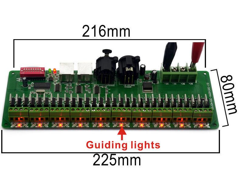
- Size: L225*W80*H32
- Gross Weight: 300g
Basic functions:
- There are 30 output channels,can connect with single or RGB lamps
- 0-100% dimming output,each channel 256 gray levels
- International standard DMX512 input protocol,address code set by DIP switches;
- Wide voltage DC input DC9V~DC24V;
- Each occupied by 30 DMX address.
- The decoder comes with 16 kinds of test patterns,16 levels for rate of change
Decoder to use: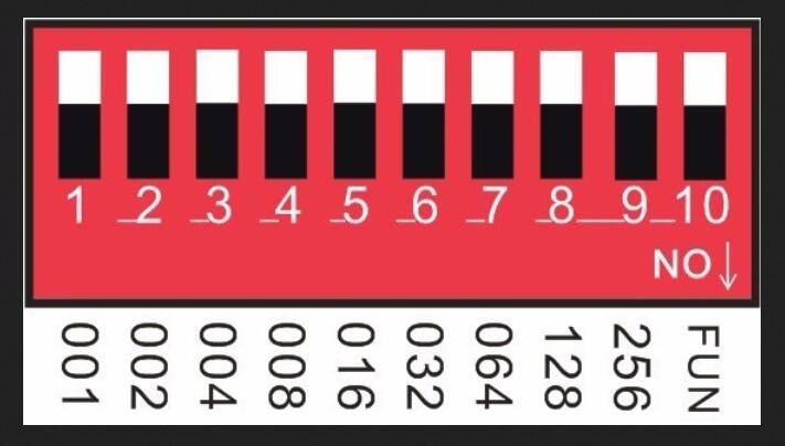
Note: FUN = OFF (the tenth code switch up) means to accept DMX512 signal mode
The first DMX address setting:
The decoder set the address bit by coding switch, of which 1-9 is for setting the start address of the Binary numeric code switch of DMX512, the first one is the lowest position,the ninth one is the highestBit of address code can be set to 255.
DMX512 start address code is the sum of switches 1-9,at the same time turn downside of the code switch (ON set to "1"),then the value of the bit can be gotten;coding switch up (set to "0"),the value of the bit is 0.
Example 1:
As the following Schematic 1,DMX512 start address is set to 38, encoding the No.6,3,2 position on switch dial to "1",others set to "0",then the sum of the switch 1-9 code value is 32 + 4 + 2,that is the DMX512 start address 38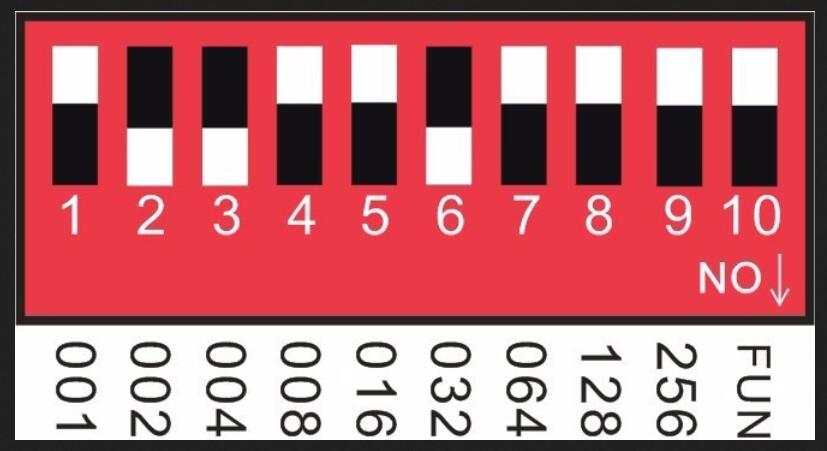
Schematic 1
Example 2:
As the schematic 2,DMX512 start address is set to 388,encoding the no.2,3,6,8 switch dial to "1",others set to "0",then the sum of the switch 1-8 code value is 4 + 128 + 256 = 388,
that is the DMX512 start address 388.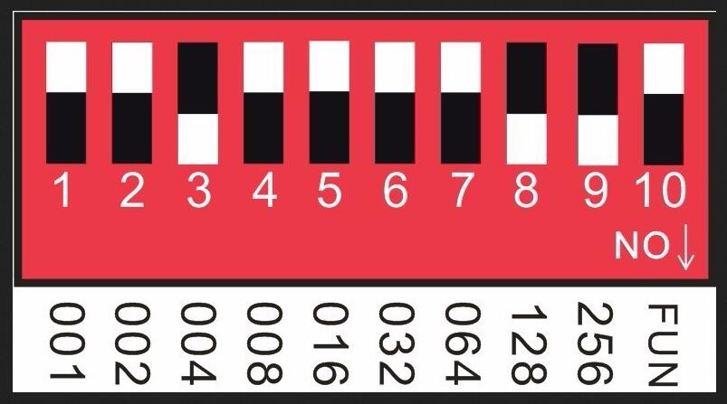
Schematic 2
Operation instruction for the automat effect 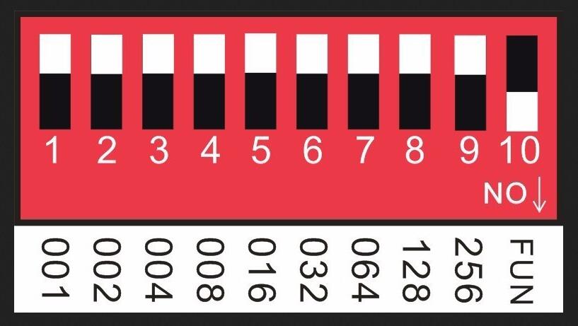
Note: It will be Automatic operation mode when the No.10 switch is turned down.
Effect choice (button switch No.1 to No.4):
1, Push No.1: Automat cycling.
2, Push No. 2: Seven-color gradual cycle changing.
3. Push No.1 &2: RGB Fade in and out
4. Push No.3: Severn color jumping
5. Push No.1 & 3: RGB jumping.
6. Push No.2 & 3: Red color.
7. Push No. 1 & 2 & 3:Green color.
8. Push No.4: Blue color.
9. Push No.1 & 4: Yellow.
10: Push No.2 & 4: Violet.
11. Push No.1 & 2 & 3: Cyan.
12. Push No.3 & 4: white.
13. Push No.1 & 3 & 4: Seven-color gradual cycle changing and jumping.
14. Push No.2 & 3 & rgb-color gradual cycle changing and jumping.
15. Push No.1 & 2 & 3 & 4: Seven-color jumping and rgb-color jumping.
Speed Choices (Button Switch No.5 to No. 8)
1. Push No.5: 0.5 second.
2. Push No.6: 1 second.
3. Push No.7: 1.5 second.
4. Push No.8: 2 second.
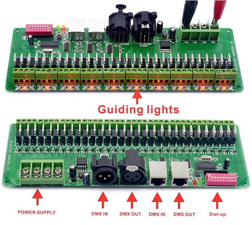
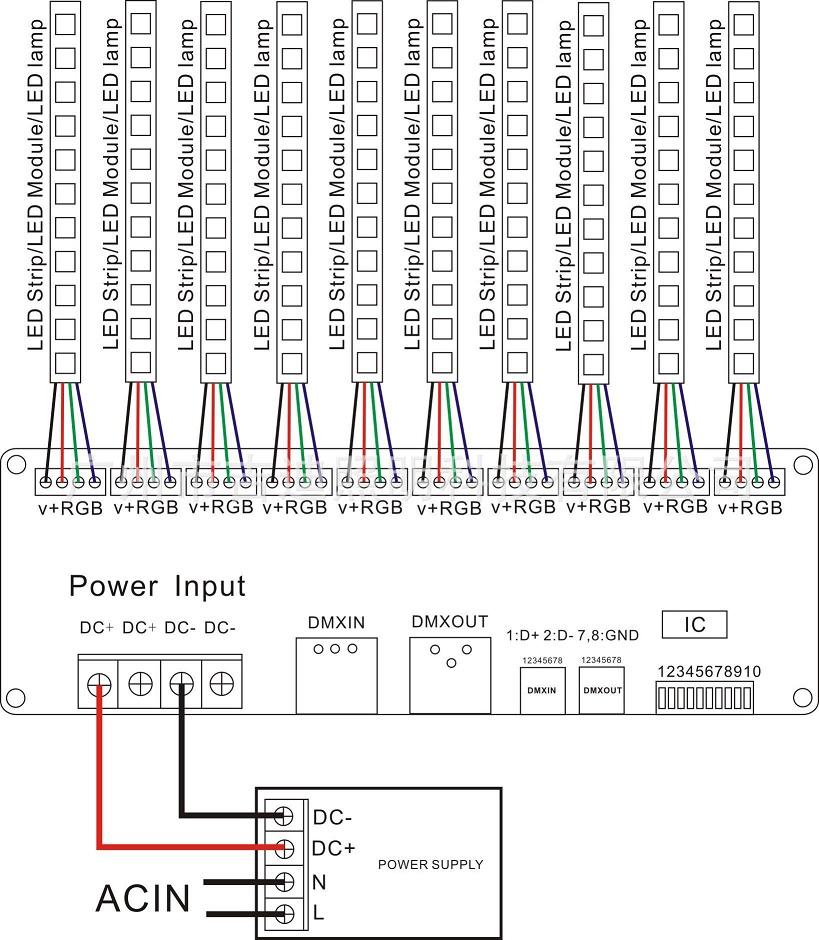
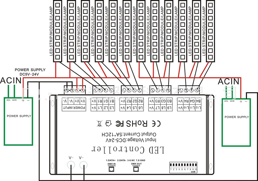
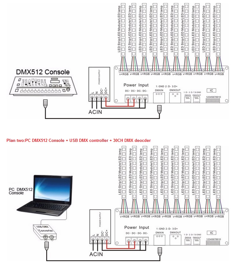
Schematic for System Connection:
Plan one:DMX512 Console + 30CH DMX deocder
Installation Notes:
1.This kind of controller works only under DC9V-24V,which is provided by the matched controllable main power,or else the controller will be damaged.
2.The UTP wire is connected hand in hand to make the cable,when two or more controller connected.
3.The power supply should be off when connecting the electric wires,and it can be turned on till making sure the wires are connected correctly and the indicator of main power in red is lighting.
4.Controller should work under the environment of adequately ventilated,dry,not corroded,no flammable gas and rust.
5.Please check the wires connection regularly so that the wires of aged,rust-eaten,and damaged insulation spacer can be replaced timely
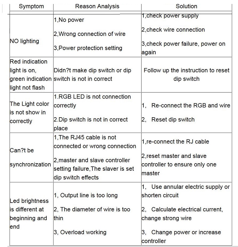
Simple troubleshooting and maintenance:
FAQ:
1.Input voltage is normal?
Ensure input voltage DC 9-24V,cathode connected DC +,negative pole DC-.When the normal power supply,the controller red indicator light on.
2.The DMX decoder controller needs DMX master control.
The controller is a DMX decoder.You must use DMX master control it.DMX master such as: USB DMX master,DMX console.
3.The decoder is not controlled?
(1) Ensure that the decoder signal line connected to right.Negative signal decoder corresponding master negative,Positive signal decoder corresponding to the master positive,GND decoder corresponding to the master GND.
(2) Ensure that the decoder is DMX mode,DIP switch tenth position must be zero.
4.How to judgement whether the decoder received DMX signal?
The decoder of the green indicator light flashes slowly or does not flash when no signal is received,indicating that the received signal when the green indicator light quick flashes.
Package List:
- 1 x 30 Channel DMX RGB LED Strip controller
- 1 x User manual


