| Quantity | 3+ units | 10+ units | 30+ units | 50+ units | More |
|---|---|---|---|---|---|
| Price /Unit | $135.31 | $132.55 | $128.41 | $122.88 | Contact US |
 4CH Machine Vision Light Controller AC 100-240V 24V 100W Designed for Industrial Product Inspection
$69.31
4CH Machine Vision Light Controller AC 100-240V 24V 100W Designed for Industrial Product Inspection
$69.31
 2CH Machine Vision Light Controller AC 100-240V 24V 60W Designed for Industrial Product Inspection
$51.82
2CH Machine Vision Light Controller AC 100-240V 24V 60W Designed for Industrial Product Inspection
$51.82
 1CH Machine Vision Light Controller AC 100-240V 24V 48W Designed for Industrial Product Inspection
$32.39
1CH Machine Vision Light Controller AC 100-240V 24V 48W Designed for Industrial Product Inspection
$32.39
3000W Induction Heater Kit with 2.4" Color Screen Built-in Power Meter and 70mL Graphite Crucible
Description:
The induction heater boasts a built-in power meter, simplifying operation. It features microsecond-level over-current and under-voltage protection, dry-run (water shortage) protection, and displays the type of protection triggered directly on the screen.
Designed to work with a DC 48V 60A power supply, this low-power induction heater is ideal for heating and quenching small iron-based metal components.
By default, it comes with a 60mm diameter heating coil designed for crucible heating.
When used with the included 70mL graphite crucible, it can reach temperatures up to 1600°C, easily melting metals such as iron, copper, gold, silver, and aluminum.
Product Features & Functions:
* Built with a 1.6mm thick military-grade PCB featuring 20oz copper for high current capacity and excellent heat dissipation
* Equipped with a 120mm high-power cooling fan for enhanced airflow
* Custom oversized high-power heatsink ensures effective cooling for the MOSFETs
* Six M4 copper posts at the output end, connected in parallel — supports not only induction coils but also high-voltage transformers or high-frequency transformers
* High-efficiency resonant circuit using six original IRFP260 MOSFETs and twelve original BM capacitors in parallel
* Capable of continuous long-term operation under proper cooling conditions
* Integrated power meter and control system make it easy to operate
* All-in-one control design eliminates complex wiring
* Induction coil wrapped in high-temperature insulation material to prevent short circuits during operation
* Microsecond-level fast over-current protection — automatically cuts off the heating circuit in case of overload.
* 2.4" color LCD display shows system parameters including voltage, current, power, operating status, and alarm types. Users can set the maximum allowable current and minimum input voltage via a potentiometer. If the system exceeds the current limit or drops below the voltage threshold, it immediately enters protection mode and locks operation. Manual reset is required to restart.
* Button-controlled interface, with support for external foot pedal control, suitable for a variety of application scenarios
* Water shortage protection for water-cooled systems
Product Specifications:
* Dimensions: 237mm × 150mm × 96mm (L × W × H)
* Heating Coil Size: 70mm × 60mm × 73mm (Inner Diameter × Outer Diameter × Height)
* Operating Voltage: 12–60V DC
* Maximum Operating Current: 60A DC
* Maximum Temperature for Direct Heating: Up to 1200°C when directly heating 20mm diameter iron rods. When using the standard 60mm diameter heating coil to heat iron, the maximum temperature is approximately 1000°C.
* Maximum Temperature with Crucible: Up to 1600°C, capable of melting iron, gold, silver, aluminum, copper, and other metals.
Package Includes:
* 1 × 3000W Main Unit
* 1 × DC 12V 2A Power Supply
* 1 × 60mm Heating Coil
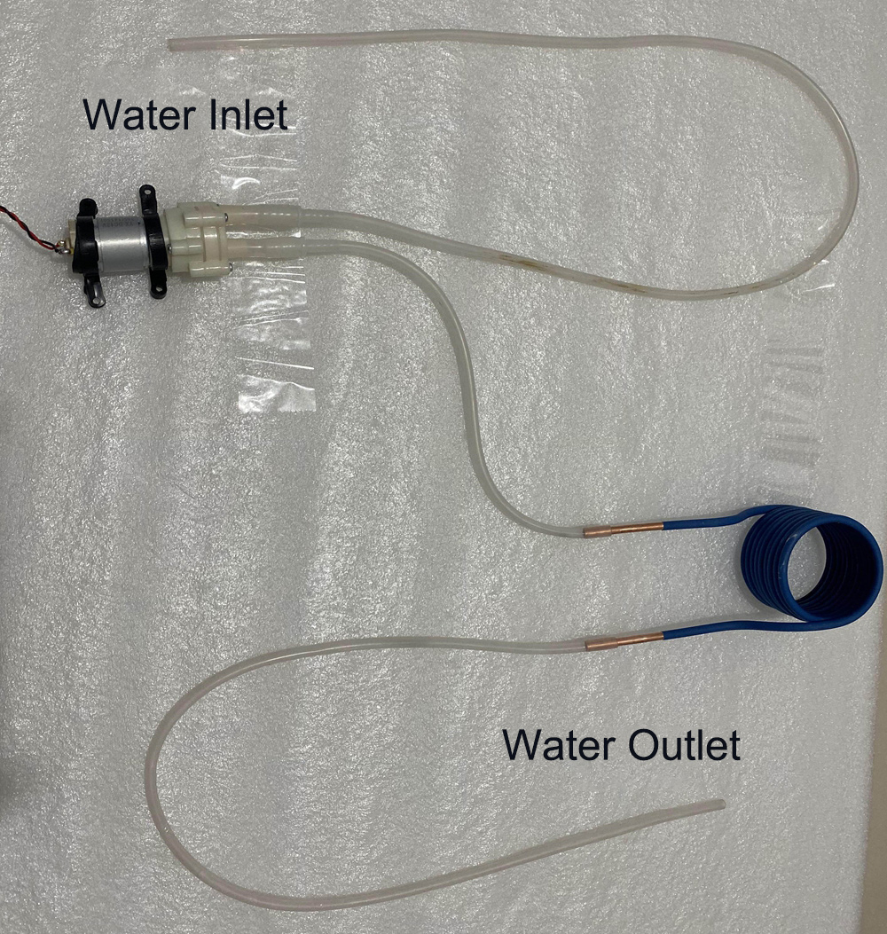
* 1 × Water Pump
* 1 × Water Pump Tube
* 1 × 70mL Graphite Crucible
Packaging Details:
* Weight: 2.5kg
Precautions:
1. The induction heating operates at high power. Besides the PCB board and electronic components generating heat, the heating coil also produces a large amount of heat. To prevent the heating coil from burning out and affecting the entire system, please be sure to use a cooling water pump designed for the heating coil.
2. It is recommended to use a power supply that meets the required power specifications; otherwise, under-voltage protection may be triggered during use. For 12V power supplies, use power above 500W; for 24V, above 1200W; for 36V, above 2000W; and for 48V, above 3000W.
3. The under-voltage threshold must not be set below 12V, and the over-current point must not exceed 60A. High power operation inevitably produces heat, so please ensure adequate heat dissipation.
4. The heating coil generates very high heat during operation. Water cooling must be used to cool the heating coil to prevent damage to the mainboard caused by high temperature.
5. The power input terminals are marked positive and negative. Do not reverse the connections!
6. Never power on without load (here, no load means the output is not connected to any load; connecting the heating coil without heating an object does not count as no load). Otherwise, the board will emit high-frequency noise and the mainboard may burn out instantly, causing complete failure.
7. When using a graphite crucible, a non-recirculating water cooling method must be used—cold water enters and hot water is discharged into the drain—to prevent prolonged high water temperature from reducing service life (this cooling method should also be used during long periods of high power operation). When heating ends, if the crucible is not removed from the heating coil, the 12V auxiliary power supply must never be cut off; otherwise, stopping the water pump will cause the heating coil to be damaged by the crucible's temperature.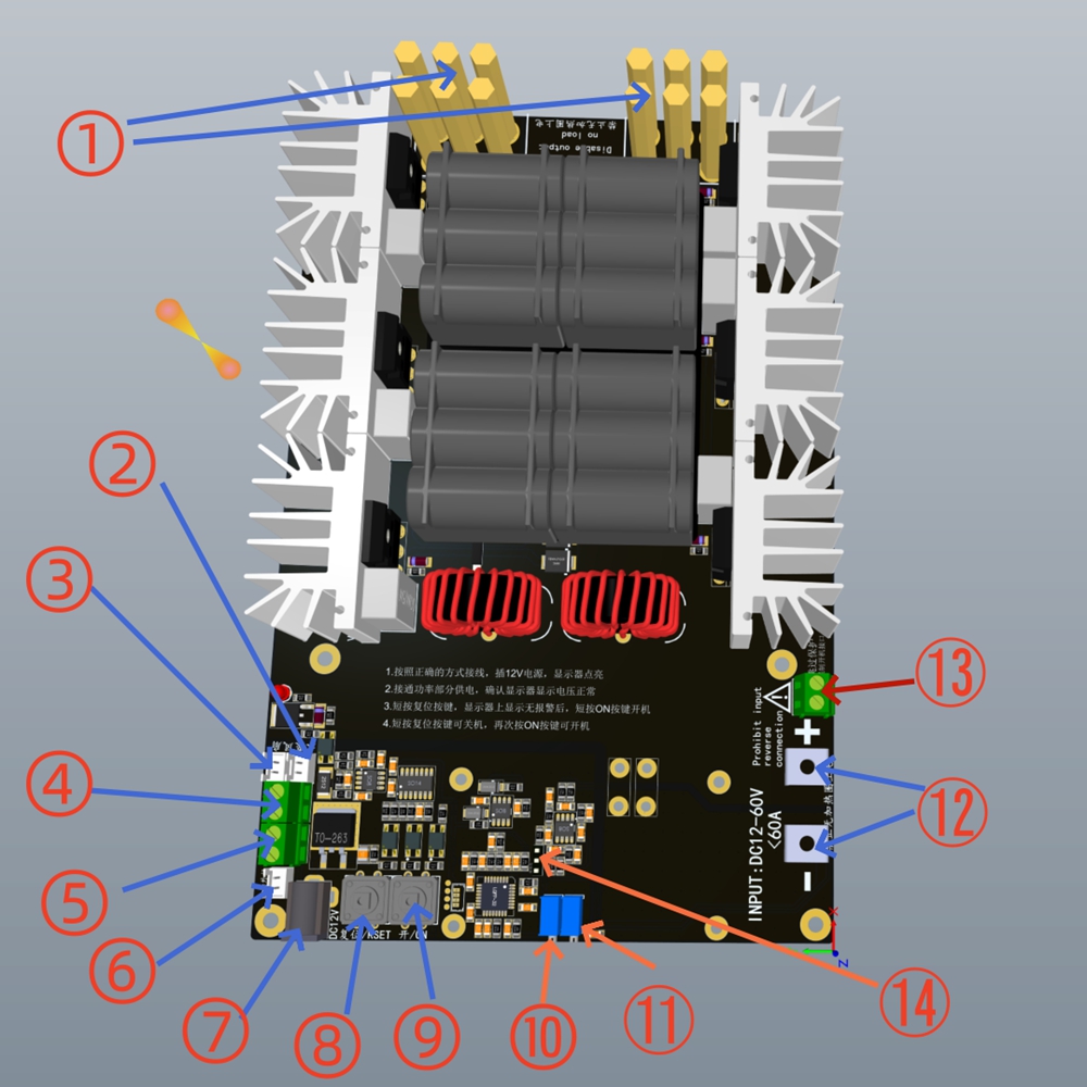
Interface Description:
① Heating coil output interfaces (must be correctly installed according to the wiring diagram)
② Water pump interface (must use the matching water pump)
③ Onboard fan interface
④ ON external connection (same function as ⑧, reserved interface for remote control)
⑤ Reset external connection (same function as ⑨, reserved interface for remote control)
⑥ Jog external connection (for connecting a foot switch, etc.; press the switch to power on, release to power off)
⑦ DC 12V 2A power input
⑧ ON button (start heating)
⑨ Reset button (turn off heating or clear alarms)
⑩ UVP adjustment potentiometer
⑪ OCP adjustment potentiometer
⑫ DC 48V power input
⑬ Forced start interface (connecting a switch can bypass alarms and force start; see instructions for details)
⑭ Water cooling alarm switch selection (can disable onboard water cooling alarm when using an external water pump)
Usage Instructions:
1. Connect the wires according to the wiring diagram, carefully check, and do not reverse connections. (The received fan and support pillars are separated from the mainboard and must be assembled correctly according to the wiring diagram.)
2. First, plug the 12V 2A power supply into AC 110V-220V, then check if the water pump and fan are working properly and if the display screen lights up.
3. If the water pump, fan, and display are all working normally, plug the DC 48V power supply into AC 220V. After waiting a few seconds, turn on the air switch (indicated by the blue arrow in the wiring diagram; this switch is optional). Observe whether the voltage displayed on the mainboard screen is around 48V.
4. If the voltage display is normal, press the reset button to clear any alarms on startup. When the display shows no alarms, press the ON button to start heating. The green indicator light will turn on, and the display will show current and status indicating heating is active.
5. To turn off heating, press the Reset button; the green indicator light will turn off, the current meter will return to zero, and the display status will show OFF.
6. This heating board has overload protection and system water shortage protection. If the water pump is not working properly or lacks water, the system will automatically protect and cut off heating. The display will show Water Shortage. If there is an over-current, the display will show Over-current. If the input voltage is under-voltage, the display will show Under-voltage.
7. The forced start switch at position ⑬ is used to force the board to start when the alarm system fails or the control circuit is damaged by connecting a switch. When using this function, always monitor the water cooling system. Interrupting water flow during use may cause damage to the board.
8. If the red light turns on and heating stops during use, check the type of alarm displayed on the screen and troubleshoot accordingly.
9. After heating stops due to current, voltage, or power alarms, and after clearing the alarm, you must press reset manually to clear the alarm before restarting heating.
10. The three interfaces ④, ⑤, and ⑥ need to be connected to self-reset switches (pressing the switch will cause it to automatically return, such as a foot switch).
11. The maximum current and minimum input voltage alarm can be set via potentiometers ⑩ and ⑪. After connecting the 12V DC power supply, you can adjust these potentiometers, and the display will show real-time values. OCP stands for over-current point, and UVP stands for under-voltage protection.
Wiring Diagram: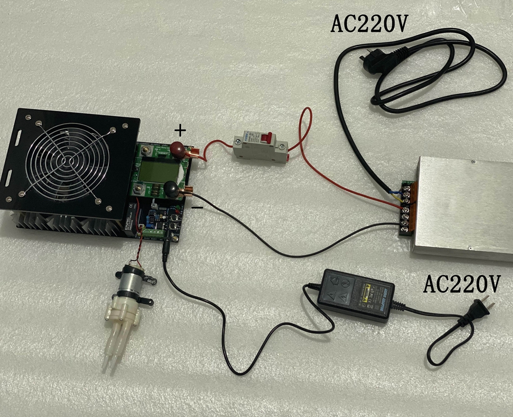


 w/ Electric Energy Meter")


