| Quantity | 3+ units | 10+ units | 30+ units | 50+ units | More |
|---|---|---|---|---|---|
| Price /Unit | $8.71 | $8.53 | $8.27 | $7.91 | Contact US |
 AD2S1210 N1 16Bit R/DC High Performance Resolver Transformer Demodulation Module 15.8Vpp Excitation Amplitude
$77.75
AD2S1210 N1 16Bit R/DC High Performance Resolver Transformer Demodulation Module 15.8Vpp Excitation Amplitude
$77.75
 GC-1201S Two-master One-slave Isolated RS485 Hub Repeater Double Electrical Isolation with 12V Power Supply
$36.58
GC-1201S Two-master One-slave Isolated RS485 Hub Repeater Double Electrical Isolation with 12V Power Supply
$36.58
 GC-1201S Two-master One-slave Isolated RS485 Hub Repeater Double Electrical Isolation Support for Modbus Protocol
$33.75
GC-1201S Two-master One-slave Isolated RS485 Hub Repeater Double Electrical Isolation Support for Modbus Protocol
$33.75
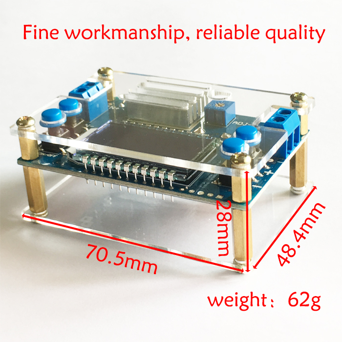
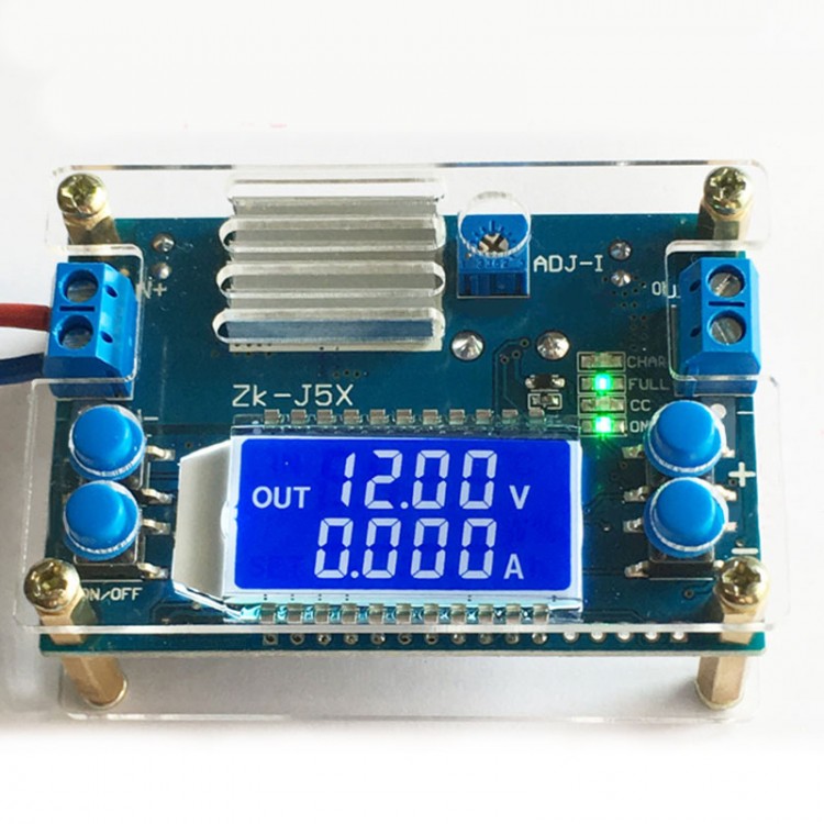
5A CNC Buck Converter Module with Shell Step Down Power Supply Module CV CC LCD Display Unassembled
Features:
- Crystal shell, beautiful and elegant design, the touch of buttons is good. You can set output voltage by buttons, which is more convenient.
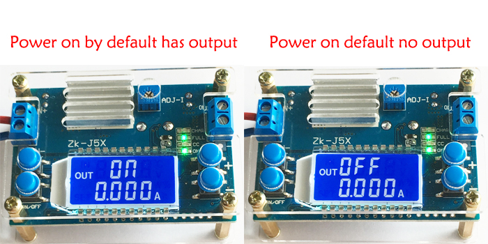
- Control output on/off by buttons. You can set power-on default to ON or OFF.
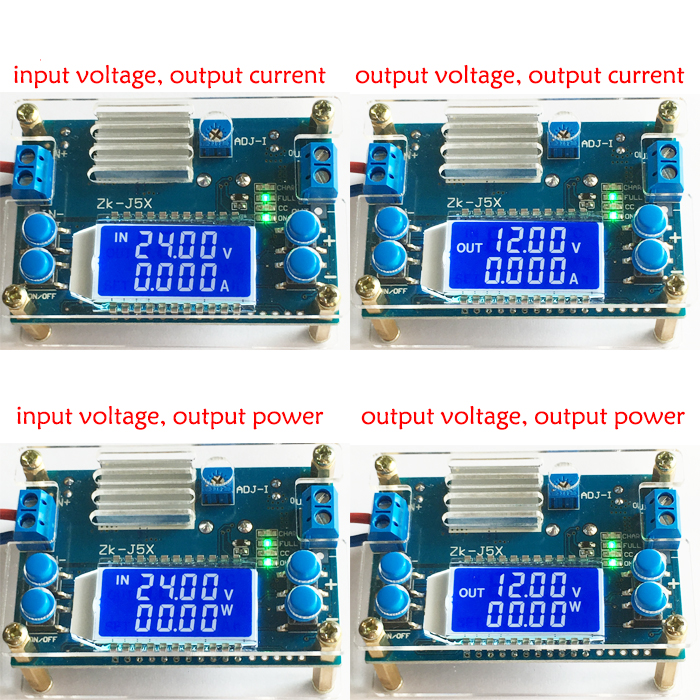
- LCD can display input and output voltage, output current and output power.
- Input terminal with reverse connection protection, the module will not burn
- High efficiency over 93%, high current, low heat, arbitrary adjustment of output voltage 1.2-32V, constant current value adjustment about 0-4.5A. Suitable for office power supply, high-power LED constant current drive etc.
Specifications:
- Input voltage: 6.5-36V (Input voltage is lower than 6.5V, current accuracy is inaccurate. LCD displays abnormally when it is lower than 5.5V.)
- Output voltage: 1.2-32V, factory default output is 5V
- Output current: can work stably at 3.5A for a long time, and can reach about 4.5A under enhanced heat dissipation (adjustable limit current is about 4.2-4.5A maximum)
- Output power: natural heat dissipation 50W (within 3.5A), enhanced heat dissipation 75W
- Voltage display: resolution of 0.05V, range of 1.2-32V, accuracy of about ±0.1V
- Current display: Resolution 0.005A, range 0-4.5A, accuracy ±0.05A
- Conversion efficiency: about 94%
- Working current: about 30mA
- Input reverse connection protection: Yes
- Output end anti-backflow: None
- Short circuit protection: Yes
Functions:
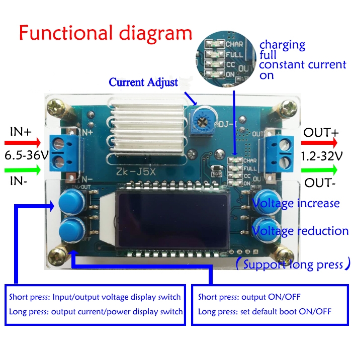
1.There are two buttons on the left of the module: IN / OUT, ON / OFF. IN / OUT button switches input voltage and output voltage display. Press and hold the button to switch output current and output power display. ON / OFF button controls output ON or OFF. Press and hold the button to set default output state to ON or OFF when it is power-on again.
There are + and-buttons on the right side of the module. Press + button once to increase output voltage by 0.05V. Press and hold it for a continuous increase, and press and hold it again for a continuous slow step to increase by 0.1V and 1V. Press - button to decrease output voltage by 0.05V. Press and hold it for a continuous decrease, and press and hold it again for a continuous slow step to decrease by 0.1V and 1V.
2. ADJ-I is a potentiometer for current setting. Turn it clockwise to increase set current. When load current reaches the set current, it enters constant current state, and CC indicator (red) is lit.
OUT indicator is an output status indicator. It is lit when there is voltage at the output, otherwise, it is off. CHAR indicator is a charging indicator, which lights up when charging. FULL indicator is a fully charged indicator. If set constant current value to 2A and charging current reaches below 0.2A, indicators will change, that is, FULL indicator will be on, and CHAR indicator will be off.
Using Methods:
1. Used as a common step-down module with over-current protection capability
(1) Press button to set output voltage to the voltage you want.
(2) First turn ADJ-I current adjustment potentiometer counterclockwise to the end. Then use a multimeter 10A current to measure output short-circuit current (just connect two test probes directly to output end). Adjust ADJ-I constant current potentiometer clockwise to make output current reach the over-current protection value you want to set. (For example, the current value displayed by a multimeter is 2A, then the maximum current when you use the module can only reach 2A. When current reaches 2A, red constant current indicator will be on, otherwise the indicator is off.)
2. Use as a battery charger
Modules without constant current cannot be used to charge battery. Due to the large voltage difference between drained battery and charger, when charging current is too large, battery will be damaged. So at the beginning, battery should be charged with constant current. When battery is charged to a certain level, it will automatically switch back to constant voltage charging.
(1) Determine floating charge voltage and charging current of the battery you need to charge (if lithium battery parameter is 3.7V / 2200mAh, then floating charge voltage is 4.2V, and the maximum charging current is 1C, which is 2200mA)
(2) Under no-load conditions, button output voltage reaches floating charge voltage; (if charging a 3.7V lithium battery, adjust output voltage to 4.2V)
(3) First rotate ADJ-I current adjustment potentiometer counterclockwise to the end, and then use a multimeter 10A current to measure output short-circuit current (just connect two test probes directly to output terminal). Adjust ADJ-I constant current potentiometer clockwise to make output current reach predetermined charging current value
(4) Connect battery and charge
(When setting steps 1, 2, and 3: when the output terminal is unloaded, do not connect battery)
Note: Battery is not included in the package.
3. Used as a high-power LED constant current driver module
(1) Determine the working current and maximum working voltage you need to drive LED;
(2) Under no-load conditions, press button to set output voltage to the maximum LED operating voltage;
(3) First turn ADJ-I current adjustment potentiometer counterclockwise to the end. Then use a multimeter 10A current to measure output short-circuit current (just connect two test probes directly to output end). Adjust ADJ-I constant current potentiometer clockwise to make output current reach predetermined LED working current;
(4) Connect LED and test.
(When setting steps 1, 2, and 3: Do not connect LED light when the output is unloaded.)
Precautions:
1. The IN- of the module is forbidden to be short-circuited with OUT-, otherwise constant current function is invalid.
2. Make sure that the power of power supply is always greater than the power required by output load. When the module is hot, please reduce the power!
3. Please read the product description carefully before using.
4. Electronic knowledge is highly recommended.
5. The product is not designed for medical, lifesaving, and life support purposes, and cannot be used in hazardous locations such as coal mine oil depots.
Package Included:
- 1 x CNC Buck Module
Note: It comes with shell and other accessories. Users need to assemble by themselves. The module is a DCDC to DC step-down module. It is not allowed to input AC voltage directly reduced by transformer. When charging battery, make sure that the output terminal of the module is powered on first and then connected to battery. After battery is fully charged, unplug battery and then power off the module to prevent battery voltage flowing backward (it is better to connect a high-current diode to the module output to prevent flowing backward). Battery is not included in the package.