| Quantity | 3+ units | 10+ units | 30+ units | 50+ units | More |
|---|---|---|---|---|---|
| Price /Unit | $100.95 | $98.89 | $95.80 | $91.68 | Contact US |
 Gravity Waves BLACK DOMAIN Tube Amp Attenuator Dummy Load Box for Tube Amplifiers ≤200W
$143.04
Gravity Waves BLACK DOMAIN Tube Amp Attenuator Dummy Load Box for Tube Amplifiers ≤200W
$143.04
 Gravity Waves Tube Amp Bunker Tube Guitar Amp Attenuator Load Box and Cab Sim Combo (Silver)
$414.91
Gravity Waves Tube Amp Bunker Tube Guitar Amp Attenuator Load Box and Cab Sim Combo (Silver)
$414.91
 20W Gravity Waves Bluespace White All-Tube Guitar Amplifier Guitar Tube Amp Combo with Stand & Pedal
$1,490.66
20W Gravity Waves Bluespace White All-Tube Guitar Amplifier Guitar Tube Amp Combo with Stand & Pedal
$1,490.66
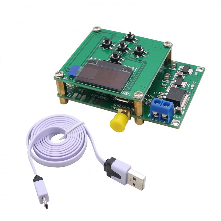
AD9912 DDS 1GSPS w/ 14-Bit DAC 400MHz Sine Wave Output AD9912 Core Board+STC Main Control Board 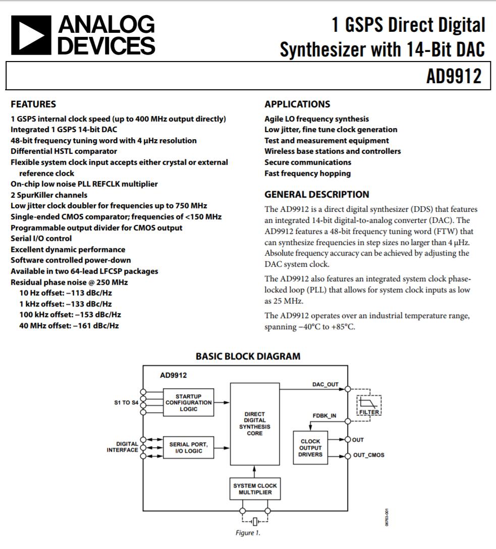
Module Parameters:
- Power Supply Voltage: +5V/400mA
- Output Frequency: 1Hz-400MHz
- Support point frequency and sweep mode, sweep parameter minimum step 1Hz, minimum time interval 1ms
- Output amplitude control word 0-1023 corresponds to output amplitude 280mVPP-1.1VPP (under 50 ohm impedance)
- Hardware supports external clock input, CMOS output, and high speed differential port output
- Provide reference code and PDF format schematic diagram for secondary development
Serial Communication Protocol:
The overall structure of the protocol adopts the command line mode, and the communication baud rate is 115200bps. The machine parses and executes, then returns the result. The command is limited to lowercase letters a~z, numbers 0~9. The end symbol of each command is the "#" character (hexadecimal notation "0x23"). The total length of the command is up to 15 characters (including "#").
W Command (write data to the main control board):
1.w1 command: set the frequency value 1 (starting frequency or point frequency)
The format is: w1xxxxxxxxx#, a total of 11 bytes. “xxxxxxxxx” is the frequency value represented by 9 digits. For example, w11000000000# indicates that the set frequency is 1000000000KHz (100MHz).
2.w2 command: set the frequency value 2 (terminating frequency). The format is: w1xxxxxxxxx#, a total of 11 bytes. "xxxxxxxxx" is the frequency value represented by 9 digits. For example, w11000000000# indicates that the set frequency is 1000000000KHz (100MHz).
3. w3 command: set the frequency value 3 (span). The format is: w1xxxxxxxxx#, a total of 11 bytes. “xxxxxxxxx” is the frequency value represented by 9 digits. For example, w11000000000# indicates that the set frequency is 1000000000KHz (100MHz).
4. wt command: Set the frequency value 1 (step value). The format is: wtxxxx#, a total of 11 bytes. "xxxx" is 4 digits representing the time value in mS. For example, wt0001# indicates that the set frequency is 1mS.
5.wv command: set the frequency value 1 (amplitude value). The format is: wvxxxx#, a total of 11 bytes. "xxxx" is 4 digits representing the amplitude control word, no dimension, only reflecting the DAC output current value of the DDS. For example, wv0001# means that the output current of the AD9912 is set to be relatively small, about 280mVpp. Wv1023# indicates that the output current of the AD9912 is set to be relatively large, about 1100mVpp.
Host sends data to PC (response value):
Return "OK$" after receiving the correct data
Package Included:
- 1 x AD9912 Core Board+STC Main Control Board