| Quantity | 3+ units | 10+ units | 30+ units | 50+ units | More |
|---|---|---|---|---|---|
| Price /Unit | $17.53 | $17.17 | $16.64 | $15.92 | Contact US |
 AD2S1210 N1 16Bit R/DC High Performance Resolver Transformer Demodulation Module 15.8Vpp Excitation Amplitude
$77.75
AD2S1210 N1 16Bit R/DC High Performance Resolver Transformer Demodulation Module 15.8Vpp Excitation Amplitude
$77.75
 GC-1201S Two-master One-slave Isolated RS485 Hub Repeater Double Electrical Isolation with 12V Power Supply
$36.58
GC-1201S Two-master One-slave Isolated RS485 Hub Repeater Double Electrical Isolation with 12V Power Supply
$36.58
 GC-1201S Two-master One-slave Isolated RS485 Hub Repeater Double Electrical Isolation Support for Modbus Protocol
$33.75
GC-1201S Two-master One-slave Isolated RS485 Hub Repeater Double Electrical Isolation Support for Modbus Protocol
$33.75
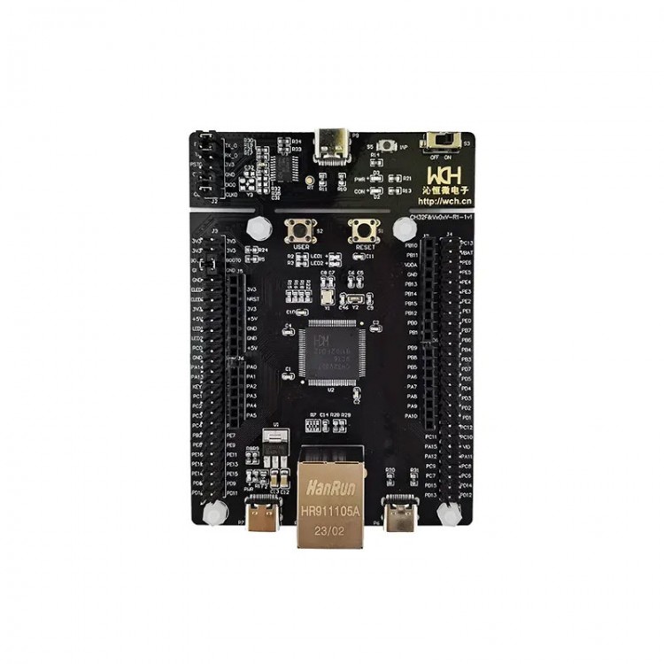
CH32V307V-EVT-R1 Evaluation Board 32-Bit MCU for RISC-V4F Processor 480Mbps PHY Development Board with WCH-Link Function
Description:
- CH32V307 is a high-capacity general-purpose micro-controller designed based on 32-bit RISC-V core, equipped with V4F core and supports single-precision floating-point instruction set for higher computing performance. It supports USB2.0 high-speed interface (480Mbps) with built-in PHY transceiver, Gigabit Ethernet MAC, etc.
- Application: Medical and health equipment, micro printers, card readers, security and monitoring alarms.
- The CH32V307V evaluation board comes with WCH-Link for online debugging and download. When using the SWD mode for program download and debugging, generally 4 wires are used, namely the power line VCC, ground wire GND, data line SWDIO, and clock line SWCLK. The SWD connection method is shown in the following figure. Short circuit the CLK and DIO, using the WCH-Link interface to download.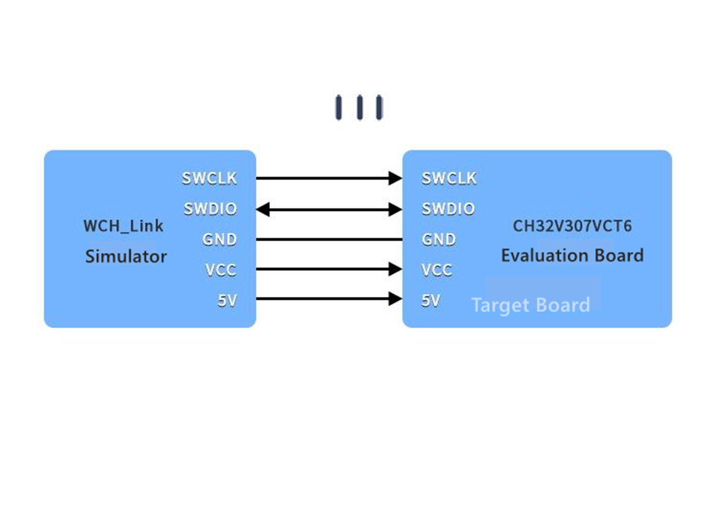
Features:
- RISC-V3A processor, up to 144MHz system main frequency
- Support single cycle multiplication and hardware division
- 64KB SRAM, 256KB CodeFlash
- Power supply range: 2.4V ~ 3.6V, GPIO synchronous power supply voltage
- Multiple low power consumption mode: sleep/stop/standby
- Power on/off reset (POR/PDR)
- Programmable voltage detector (PVD)
- 14-Channel DMA controller
- 16-Channel TouchKey channel monitoring
- 16-Channel 12-bit ADC conversion channel
- 2-Channel 12-bit DAC conversion channel
- 4 groups of OPA (operational amplifier)
- One group of random number generator
- 7 Timers
- 1 x USB2.0 full speed host/device interface
- 1 x USB2.0 high speed host/device interface
- 2 x CAN interface (support Master and Slave mode)
- 2 x IIS interface (support for SMBus/PMBus)
- 1 x ETH interface
- 8 x U(S)ART interface
- 3 x SPI interface (support Master and Slave mode)
- 80 I/O interfaces, all I/O ports can be mapped to 16 external interrupts
- CRC calculation unit, 96-bit chip ID
- Serial single wire debugging (SWD) interface
Routines:
- External interrupt line routine
- Flash erase/read/write, as well as fast programming
- GPIO routine
- I2C-7/10bit Address Mode Routine
- Low power consumption - sleep/standby/shutdown mode routine
- Clock source selection/MCO pin clock output routine
- SPI single line half duplex/double line full duplex mode routine
- Calendar Routine
- Complementary output and dead band insertion mode routines
- External trigger synchronous start of two timer routines
- Input catch/single pulse output/output comparison/PWM output routine
- Reset/gate control/trigger and other slave mode routines
- Timer using DMA routines
- For TouchKey detection routine
- DMA/Half Duplex/Hardware Flow Control/Interrupt/Multi processor Communication/Polling Transceiver/Serial Port Printing Debugging Example/Synchronization Routine for USART
- USBHD/DIVICE Module CH372/HOST-USB Device Enumeration/USB File System Routine for USB
- WWDG Window Watching Dog Routine
- Independent watchdog routine
- OPA4 voltage follower process
- DVP operation 0V2640 camera video mode displaying image on LCD routine
- DVP operation OV2640 camera JPEG mode routine
- Noise/sine wave/square wave/ordinary output routine for DAC
- ETH physical layer sends and receives Ethernet frames/uses external MII/RMII interface physical layer sends and receives Ethernet frames/demonstrates routines
- ETHTcp (Client/Server)/UDP (Client/Server) receives data and sends back demonstration after connecting to the client routines
- For HarmonyOS porting routine
- SDIO Operation SD Card Routine
- Random Number Generator Routine
- Independent Word Speech Recognition Routine
FAQ:
Q: How can I download through USB or serial port?
A: BOOT0 is connected to a high level, connected to a computer or P8 serial port through any U port on the board, and then connected to a computer through a USB transfer tool. The program is written through the computer's ISP tool. After programming, if you run the target program, you need to connect BOOT0 to the ground.
CH32V307 Data sheet:
- http://www.wch.cn/downloads/CH32V20x_30xDS0_PDF.html
Package Included:
- 1 x CH32V307V-EVT-R1 Board
Note:
- Other boards displayed in the picture are not included.


 PIX 2.4.8 for RC Quadcopter and 6-8 Axis Multirotor")


