| Quantity | 3+ units | 10+ units | 30+ units | 50+ units | More |
|---|---|---|---|---|---|
| Price /Unit | $212.27 | $207.94 | $201.44 | $192.77 | Contact US |
 M5Stack Paper S3 E-Paper Display Touchable Low Power Consumption 4.7-inch E-ink Display Development Kit ESP32S3
$87.42
M5Stack Paper S3 E-Paper Display Touchable Low Power Consumption 4.7-inch E-ink Display Development Kit ESP32S3
$87.42
 LILYGO Grey Shell Version T-Display-S3 1.9-inch LCD Display Development Board WiFi Bluetooth5.0 Wireless Module for Arduino
$32.47
LILYGO Grey Shell Version T-Display-S3 1.9-inch LCD Display Development Board WiFi Bluetooth5.0 Wireless Module for Arduino
$32.47
 Sketchboard Mechanical Arm Plotter Robot Arm Students Programming Learning DIY Kit for Arduino
$44.05
Sketchboard Mechanical Arm Plotter Robot Arm Students Programming Learning DIY Kit for Arduino
$44.05
The purpose of this manual is to describe the functionality and contents of the AX309
development board. This document includes instructions for operating
the board, descriptions of the hardware features, and explanations of
the test code programmed into the on-board programmable memory. For
reference design documentation and example projects, see the official
website:www(dot)LogiFind(dot)com
The AX309 development board provides a complete hardware environment
for designers to accelerate their time to market.The kit delivers a
stable platform to develop and test designs targeted to the low-cost
and low-power Xilinx Spartan-6 FPGA. The installed Spartan-6 FPGA LX9
device offers a prototyping environment to effectively demonstrate the
enhanced benefits of low-cost Xilinx FPGA solutions. Reference
designs are included with the kit to exercise standard peripherals on
the evaluation board for a quick start to device familiarization.
The AX309 development board contains the following individual pieces:
--The easyFPGA-Spartan-6 development board
--USB 2.0 cable
--Xilinx ISE® Design Suite (IDS) 14.7
--Example Source Code
--AX309 Development Board Users Manual
--Transparent protection board
Please note that this kit does NOT include a Xilinx programming cable.
Figure 1 gives the block diagram of the AX309
development board. To provide maximum flexibility for the user, all
connections are made through the Xilinx Spartan-6 FPGA device. Thus,
the user can configure the FPGA to implement any system design.
Figure 1.Block Diagram 
Following is more detailed information about the blocks in Figure 1:
FPGA
--Xilinx Spartan-6 XC6SLX9 FPGA
JTAG Port
--On-board JTAG Port for programming
SDRAM
--256Mbit SDRAM
SPI Flash memory
--64Mbit SPI FLASH
Camera Port
--Supports 5000000 pixels OV5640 module
Pushbutton switches
--4 User Keys
--Normally high; generates one active-low pulse when the switch is pressed
General User Interfaces
--4 User LEDs
--6-digit 7-segment displays
--Buzzer
System Clock inputs
--50MHz oscillator
RTC Module
--Comes with a CR1220 battery socket
External Eeprom
--Comes with a 24LC04;
VGA output
--Uses a 16-bit resistor-network DAC under RGB65536 Mode
--With 15-pin high-density D-sub connector
Voltage Regulator Circuit
--Provides 1.2V,5V and 3.3V for system power supply
Micro SD
--Equips a Micro SD card holder.
On-board USB to TTL/RS232 Module
--Use cp2102 for USB-TTL/RS232 Converting (Without DB-9 serial connector)
40-PIN Expansion Headers
--Two Channels 40-PIN Expansion Headers Spartan-6 I/O pins, as well
as 3 power and ground lines, are brought out to the 40-pin expansion
connectors. You can install 4.3”TFT module and AD/DA module by our
company on this two expansion headers.

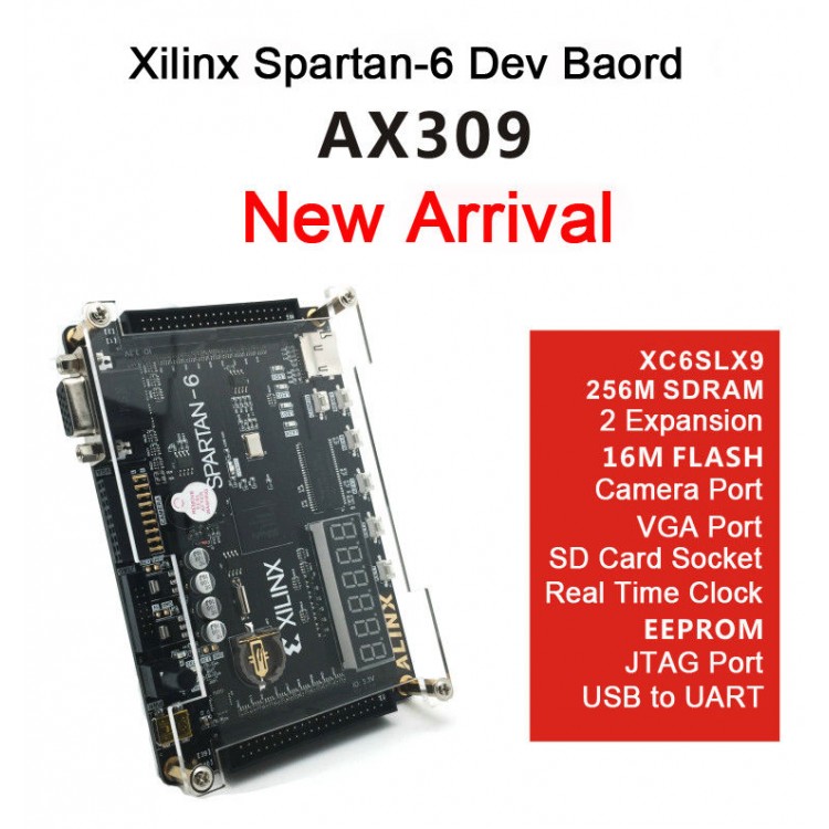
A photograph of the AX309 development board is shown in following Figure 3. It depicts the layout of the board and indicates the location of the connectors and key components.
The following hardware is provided on the AX309 development board:
Tab1.Baord Source
1 |
Xilinx XC6SLX9 |
2 |
256Mbit SDRAM |
3 |
FLASH 16Mbit |
4 |
USB to UART cp2102 |
5 |
USB/USB Power |
6 |
Power Switch |
7 |
JTAG Port |
8 |
Camera Port |
9 |
VGA Port |
10 |
SD card |
11 |
RTC DS1302 |
12 |
Reset and 4 User Buttons |
13 |
6-digit LED Display |
14 |
EEPROM 24LC04 |
15 |
4 User LEDs |
16 |
50Mhz System Clock |
17 |
Buzzer |
18 |
Power Circuit |
19 |
40PIN Expansion Port |
20 |
40PIN Expansion Port |
We provide easy-to-read pdf in english for you.