ASG102 Digital Handheld Signal Generators 2 Channels Car Automotive Signal Generator Kit With CAN data function
New Jinhan ASG102 Digital Handheld Signal Generators 2 Channels
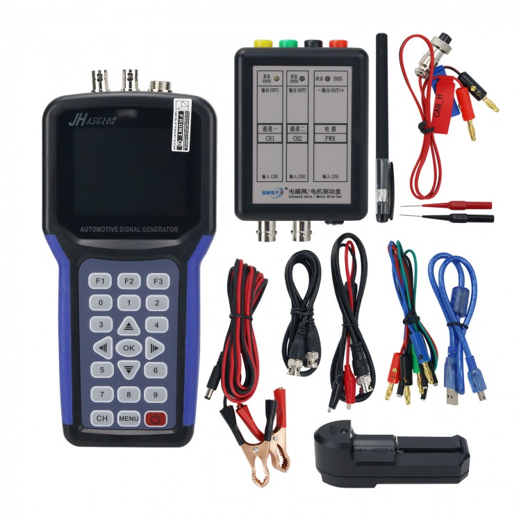
JHASG102 Automotive Signal Generator Kit With CAN data function

1.Interface introduction
(1) Button description and main functions:
F1: It is mainly used to switch between the first and fourth items.
Or to switch the value of the selected item.
F2: It is mainly used to switch between the 2nd and 5th items, or
to switch the value of the selected item.
F3: It is mainly used to switch between the 3rd and 6th items, or
to switch the value of the selected item.
OK: Determine the button for confirmation or save.
: Up button for up selection or value increase.
: Down button for down selection or value reduction.
: Left button for moving one item (bit) to the left.
: Right button to move one item (bit) to the right.
CH : It is mainly used for switching between channel 1 and channel 2
configuration interfaces.
MENU: Mainly used to return to the menu selection interface.
0-9: The number key changes the corresponding digit value to a numeric
key value.
: On/off.
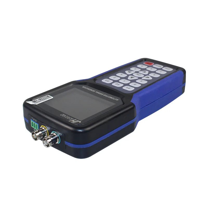
(2) Port description:(Figure 1-1)
CH1: Channel 1 signal output.
CH2: Channel 2 signal output.
CAN: CAN data receiving end.
Figure 1-1
(3) Instrument features:
According to the automotive rules and actual needs of on-site
diagnosis, the instrument summarizes and analyzes the characteristics of
existing car signal generators:
1. The signal characteristics can be adjusted in real time: the signal
can be adjusted at any time by adjust waveform, amplitude, frequency,
missing teeth and other indicators. This feature greatly helps to
determination of the fault in the vehicle maintenance process.
2. Two-channel waveform signal output can simultaneously output signals
of different frequencies, amplitudes and waveforms within two bandwidths.
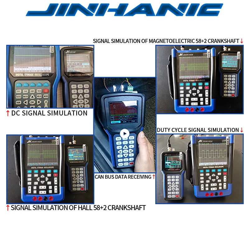
3. CAN bus function:
It is mainly used to test whether the CAN bus of various models is in
normal communication. The test rate is 10K, 20K, 33.3K, 50K, 62.5K,
83.3K, 125K, 250K, 500K, 1M.
4. Friendly HMI: the instrument adopts the most simple design idea,
320*240 large-screen liquid crystal display, the display interface logic
is clear; the panel operation is clear, which is convenient for the
operator to quickly carry out various operations.
5. the appearance is small and convenient, using over injection molding,
good use of feel. The internal components are all imported, users can use
it with confidence!
(II) Main interface operation
1. After the instrument is turned on, enter the main operation interface
(Figure 1-2). Press any button (except on/off key), the first item
(channel 1) will be selected by default.
2. Then use the “ ” button to switch the selected item.
3. After selecting the item, press the OK button to enter the corresponding
configuration interface.
Figure 1-2
(III) Signal generator operation
After booting into the main interface, press the button to select
“Channel 1” or “Channel 2”, then press “OK” to enter the signal
generator parameter setting interface. The signal generator operation
interface is shown in
Figure 1-3 Figure 1-4
Mainly configure output signal parameters such as frequency, amplitude,
duty cycle, waveform, X, Y.
1.Waveform selection
Press F1 to select the first item (“Waveform”), then use the “ ”
or“ ” key or the direct numeric key to input the value (range 1-5,
a total of 5 waveforms) to select the waveform to be output. The serial
number can be seen on the display. Corresponding waveform. The waveform
and corresponding serial number are as shown below:
2. Setting frequency
Press the F2 key to select the “Frequency” item, use the “ ”
or “ ”key to select a value of the frequency, and then add or subtract
the value by “ ” or “ ” step or change the value by directly using
the number keys.
Note: The frequency value ranges from 1HZ to 8000HZ.
3. Set the amplitude
Press the F3 key to select the “Amplitude” item, use the “ ” or
“ ” key to select a certain value of the amplitude, and then use the
“ ” or “ ” key to increase or decrease the value step by step of
the bit or directly change the value by the number key.
Note: The amplitude value ranges from 0V to 20V.
4.Set the duty cycle
Press the F3 key to select the “Amplitude” item, use the “ ” or
“ ” key to select a certain value of the amplitude, and then use the
“ ” or “ ” key to increase or decrease the value step by step of
the bit or directly change the value by the number key.
5. Set the X value
X represents the number of sine waves or square waves.
Press the F2 key to toggle the “X” item, use the “ ”or “ ”
key to select a value of X, and then press the “ ” or “ ” key
to step up or subtract the value or change the value directly by the number
key.
Note: The X value range is 1-199.
6. Set the Y value
Y represents the number of straight lines.
Press the F3 key to toggle the “Y” item, use the “ ” or “ ”
key to step up or subtract the bit value or change the bit value directly
by the number keys.
Note: Y value range is 0-9.


 USBCAN-OBD Portable Automotive Decoding Single Channel USB CAN Analyzer Dedicated for Automotive OBDII
$41.13
USBCAN-OBD Portable Automotive Decoding Single Channel USB CAN Analyzer Dedicated for Automotive OBDII
$41.13
 AERMOTOR EM415PRO 6-42V Car Short Open Circuit Detector Automotive Circuit Tester without Oxford Bag
$15.41
AERMOTOR EM415PRO 6-42V Car Short Open Circuit Detector Automotive Circuit Tester without Oxford Bag
$15.41
 MAYILON MY6770 Automotive Coating Thickness Gauge Paint Thickness Gauge Fe/NFe 0-1300µm Tester
$39.11
MAYILON MY6770 Automotive Coating Thickness Gauge Paint Thickness Gauge Fe/NFe 0-1300µm Tester
$39.11