| Quantity | 3+ units | 10+ units | 30+ units | 50+ units | More |
|---|---|---|---|---|---|
| Price /Unit | $65.52 | $64.19 | $62.18 | $59.51 | Contact US |
 H2MD DC24-120V 6A Engraving Machine CNC Stepper Motor Driver Module Support Phase Dislocation Protection
$45.54
H2MD DC24-120V 6A Engraving Machine CNC Stepper Motor Driver Module Support Phase Dislocation Protection
$45.54
 ZM-3H2080 24V High Performance 3-Phase Stepper Motor Driver Controller AC80-220V for 86-130MM Stepper Motors
$166.32
ZM-3H2080 24V High Performance 3-Phase Stepper Motor Driver Controller AC80-220V for 86-130MM Stepper Motors
$166.32
 ZM-3H2080 12V High Performance 3-Phase Stepper Motor Driver Controller AC80-220V for 86-130MM Stepper Motors
$166.32
ZM-3H2080 12V High Performance 3-Phase Stepper Motor Driver Controller AC80-220V for 86-130MM Stepper Motors
$166.32
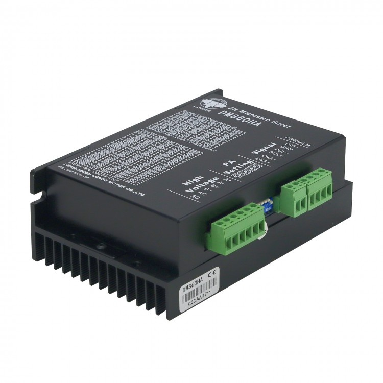
DM860HA 2H Microstep Driver Stepper Motor Driver 7.8A 128 Subdivision For 57 85 86 Stepper Motors
Description:
DM860HA subdivided two-phase hybrid stepping motor driver adopts DC 24-80V power supply, suitable for driving 24V-80V, less than 8.0A two-phase hybrid stepping motor with outer diameter 57-110mm/2.2-4.3". This drive uses the current loop of the AC servo drive for subdivision control. The torque fluctuation of the motor is very small, the low-speed operation is very stable, and there is almost no vibration and noise. At high speed, the torque is also much higher than other two-phase drives, and the positioning accuracy is high. It is widely used in engraving machines, CNC machine tools, packaging machinery and other equipment with high resolution requirements.
Features:
1. Average current control, two-phase sinusoidal current drive output
2. DC 24-80V power supply
3. Photoelectric isolation signal input/output
4. With overvoltage, undervoltage, overcurrent, overheating, and phase-to-phase short-circuit protection functions
5. Fourteen-speed subdivision and automatic half-flow function
6. Eight output phase current settings
7. With offline signal input terminal
8. High starting speed, high high-speed torque
Electrical Parameters:
- Input voltage: DC 24~80V input
- Input current: less than 6 amps
- Output current: 2.8A~7.8A
- Power consumption: 80W; internal insurance: 10A
- Temperature: working temperature -10 to 45℃; storage temperature -40℃ to 70℃
- Humidity: No condensation, no water droplets
- Gas: No combustible gas and conductive dust
- Weight: about 500 grams
Package Included:
- 1 x Set of Stepping Motor Driver
Control Signal Interfaces:
Figure 1 is the wiring schematic diagram of the driver
1. Definition of Control Signal:
* PUL/CW+: Step pulse signal input positive terminal or CW step pulse signal input positive terminal
* PUL/CW-: Step pulse signal input negative terminal or CW step pulse signal input negative terminal
* DIR/CCW+: Step direction signal input positive terminal or CCW step pulse signal input positive terminal
* DIR/CCW-: Step direction signal input negative terminal or CCW step pulse signal input negative terminal
* ENBL+: Offline enable reset signal input positive terminal
* ENBL-: Offline enable reset signal input negative terminal
* When the offline enable signal is valid, the drive fault is reset, any valid pulse is prohibited, the output power element of the drive is turned off, and the motor has no holding torque
2. Control Signal Connection:
The control signal of the host computer can be effective at high level or at low level. When high level is effective, connect the negative ends of all control signals together as the signal ground; when low level is effective, connect the positive ends of all control signals together as the signal common end. Now take the open collector and PNP output as an example, the interface circuit diagram is as follow:
Controller open collector output
Figure 1. Input interface circuit (common anode connection)
Figure 2. Input interface circuit (common cathode connection)
Controller PNP output
Attention:
- When the VCC value is 5V, R is short-circuited;
- When the VCC value is 12V, R is 1K, which is greater than 1/8W resistance;
- When the VCC value is 24V, R is 2K, which is greater than 1/8W resistance;
- R must be connected to the signal terminal of the controller.
Function Selection (realized by DIP switch on the driver panel):
1. Set the number of steps per revolution of motor:
The driver can set the number of steps per motor revolution to 400, 800, 1600, 3200, 6400, 12800, 25600, 51200, 1000, 2000, 5000, 10000, 25000, 50000 steps respectively. Users can set the number of steps of the driver through the SW5, SW6, SW7, SW8 bits of the DIP switch on the front panel of the driver (as shown in the table below):
2. Selection of Control Method:
DIP switch SW4 can be set into two control modes:
- When set to OFF, it has a half-flow function.
- When set to ON, there is no half-flow function.
3. Set Output Phase Current:
In order to drive stepper motors with different torques, users can set the output phase current (effective value) of the drive in amperes through the DIP switches SW1, SW2, and SW3 on the drive panel, and the output current corresponding to each switch position. The output current value corresponding to different types of drivers is different. The details are shown in the table below.
4. Semi-Flow Function:
The half-current function means that after 200ms without step pulse, the output current of the driver automatically drops to 40% of the rated output current to prevent the motor from heating.
Power Interfaces:
1. VDC, GND: connect the drive power
- VDC: DC power supply +. The power supply voltage is DC 24~80V. The maximum current is 6A
- GND: DC power supply -
2. A+ A- B+ B-: Connect a two-phase hybrid stepping motor
- The connection of the driver and the two-phase hybrid stepping motor adopts a four-wire system. The motor windings have parallel and series connection, and the parallel connection method has good high-speed performance, but the driver current is large (1.73 times the current of the motor winding)
- In series connection, the driver current is equal to the motor winding current
Installation:
There should be a space of 20mm/0.8" around, and it should not be placed next to other heating equipment. Avoid dust, oil mist, corrosive gas, excessive humidity and strong vibration
Troubleshooting:
1. Status light indication
- PWR: Green light on during normal operation
- ALM: Red light on when fault occurs. Motor phase-to-phase short-circuit, overvoltage protection, overheating protection and undervoltage protection
2. Failure & Reasons & Solutions:
LED does not light up
A. The power connection is wrong: please check the power supply connection
B. Low power supply voltage: Please increase the power supply voltage
The motor does not rotate, and there is no holding torque
A. The motor connection is incorrect: correct the motor connection
B. Offline enable RESET signal is valid: make RESET invalid
The motor does not rotate, but there is a holding torque:
A. No pulse signal input: adjust pulse width and signal level
Wrong direction of motor rotation:
A. The phase sequence of the power line is connected incorrectly: interchange any two connected lines
B. The direction signal input is wrong: change the direction setting
Motor torque is too small:
A. The phase current setting is too small: Set the phase current correctly
B. Acceleration too fast: reduce the acceleration value
C. Motor blocked: eliminate mechanical failure
D. The driver does not match the motor: replace with a suitable driver
Driver Wiring:
A complete stepper motor control system should contain stepper drives, DC power supplies and controllers (pulse sources). The following is a typical system wiring diagram: