| Quantity | 3+ units | 10+ units | 30+ units | 50+ units | More |
|---|---|---|---|---|---|
| Price /Unit | $36.15 | $35.41 | $34.31 | $32.83 | Contact US |
 M5Stack Paper S3 E-Paper Display Touchable Low Power Consumption 4.7-inch E-ink Display Development Kit ESP32S3
$87.42
M5Stack Paper S3 E-Paper Display Touchable Low Power Consumption 4.7-inch E-ink Display Development Kit ESP32S3
$87.42
 LILYGO Grey Shell Version T-Display-S3 1.9-inch LCD Display Development Board WiFi Bluetooth5.0 Wireless Module for Arduino
$32.47
LILYGO Grey Shell Version T-Display-S3 1.9-inch LCD Display Development Board WiFi Bluetooth5.0 Wireless Module for Arduino
$32.47
 Sketchboard Mechanical Arm Plotter Robot Arm Students Programming Learning DIY Kit for Arduino
$44.05
Sketchboard Mechanical Arm Plotter Robot Arm Students Programming Learning DIY Kit for Arduino
$44.05
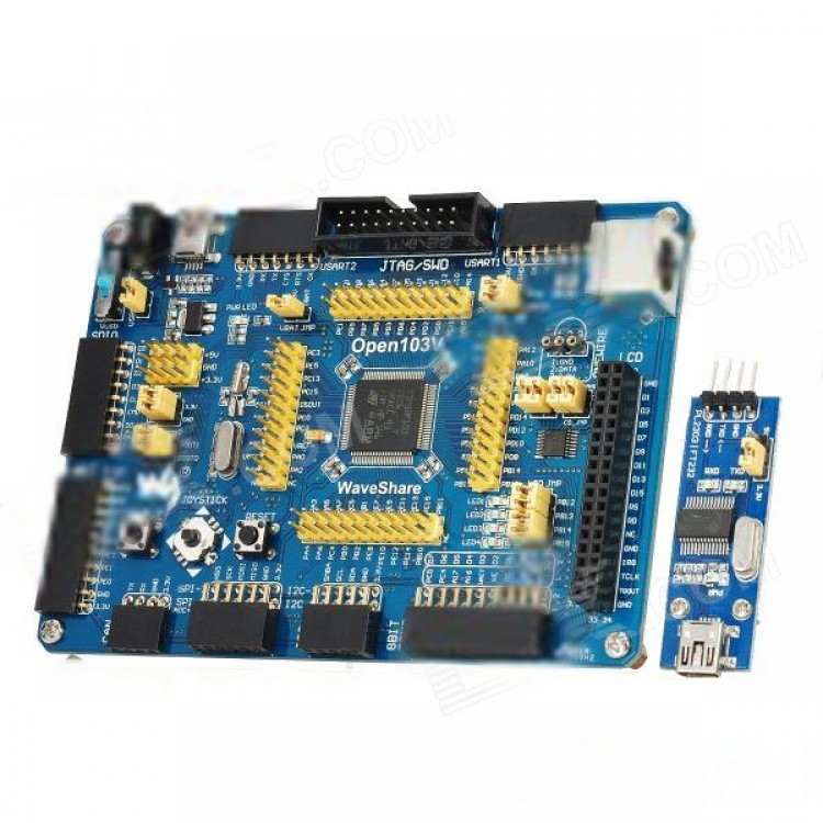
Open103V Standard STM32F103VET6 ARM Cortex-M3 SCM Development Board w/ PL2303 USB UART Module
Specfication:
- Color: Blue
- Material: PCB
- Open103V Standard is a STM32 development board that features a STM32F103VET6 device as the microcontroller
- It supports further expansion with various optional accessory boards for specific application
- The modular and open design makes it the ideal for starting application development with STM32F family
- 1. STM32F103VET6: the high performance STM32 MCU in TQFP100 package which features
- Core: ARM Cortex-M3 32-bit RISC
- Operating Frequency: 72MHz, 1.25 DMIPS/MHz
- I/Os: 80
- Operating Voltage: 2-3.6V
- Memories: 512K Flash, 64K RAM (the highest specification in STM32F103V series)
- Communication Interfaces: 3xSPI, 5xUSART, 2xI2S, 2xI2C, 1xFSMC, 1xLCD, 1xSDIO, 1xUSB, 1xCAN
- AD & DA converters: 3xAD (12bit, 1us, shares 16 channels 2xDA (12bit)
- Debugging/Programming: supports JTAG/SWD (serial wire debug) interfaces, supports IAP
- 2. 74LVC139: Used for FSMC expansion, makes it possible to connect multi peripherals through FSMC at the same
time, such as connecting a LCD and a NAND FLASH
- 3. AMS1117-3.3V: 3.3V voltage regulator
- 4. Power supply switch: 5V DC or USB
- 5. Power indicator
- 6. LEDs: Convenient for indicating I/O status or program debugging running state
- 7. Reset button
- 8. User key
- 9. Joystick: Convenient for I/O input (five directions)
- 10. 32.768K crystal oscillator: for internal RTC
- 11. 8M crystal oscillator: enables the MCU run at 72M frequency by frequency multiplication
- 12. SDIO Interface: connects to the Micro SD Board easily, It is much faster to read/write the Micro SD card via
SDIO than via SPI
- 13. 8-Bit I/O Interface: easily connects to keypad, motor, etc
- 14. CAN Interface: communicates with accessory boards which feature the CAN device conveniently
- 15. SPI Interface: easily connects to SPI peripherals such as FLASH (AT45DBxx), SD card, MP3, etc
- 16. I2C Interface: easily connects to I2C peripherals such as I/O expander(PCF8574), EEPROM (AT24Cxx), etc
- 17. NAND FLASH Interface: easily connects to the NAND FLASH peripherals
- 18. LCD Interface: easily connects to the touch screen LCD
- 19. ONE-WIRE Interface: easily connects to ONE-WIRE devices (TO-92 package), such as temperature sensor (DS18B20),
EEPROM (DS2401), etc.
- 20. PS/2 Interface: easily connects to PS/2 keyboard or mouse
- 21. USART1 Interface: easily connects to RS232, RS485, USB TO 232
- 22. USART2 Interface: easily connects to RS232, RS485, USB TO 232
- 23. USB Port: USB communication between board and PC
- 24. 5V DC jack
- 25. 5V/3.3 V power input/output
- 26. MCU pins connector: all the MCU pins are accessible on expansion connectors for further expansion
- 27. JTAG/SWD interface: for debugging/programming
- 28. Boot Mode Selection: for configuring the BOOT0 and BOOT1 pins
- 29. USB Enable Jumper
- Short circuit jumper to enable the PC auto detection while USB connecting
- Disconnect the jumper to disable function
- 30. PS/2 Interface Jumper
- Short circuit jumper to connect the PS/2 device to default I/Os
- Disconnect the jumper to connect the PS/2 device to custom I/Os via DuPont wires
- 31. LEDs Jumper
- Short circuit jumper to connect the LEDs to default I/Os
- Disconnect the jumper to connect the LEDs to custom I/Os via DuPont wires
- 32. VBAT Selection Jumper
- Short circuit jumper to use system power supply
- Disconnect the jumper to connect the VBAT to external power, such as battery
- 34. 74LVC139 Selection Jumper (used for FSMC chip selection)
- Short circuit the jumper to connect to default I/Os used in example code
- Disconnect the jumper to connect to custom I/Os via jumper wires
Packing list:
- 1 x Open103V development board
- 1 x PL2303 USB UART Board (mini)
- 1 x USB Cable (mini / 195cm)
- 2 x 4-pin wire (18cm)
- 2 x 2-pin wire (18cm)
- 1 x Power adapter (AC 100~240V / 2-flat-pin plug / 145cm-cable)
- 1 x User Guide CD