| Quantity | 3+ units | 10+ units | 30+ units | 50+ units | More |
|---|---|---|---|---|---|
| Price /Unit | $19.31 | $18.91 | $18.32 | $17.53 | Contact US |
 DM40B Standard Version 10Hz-50MHz Portable Digital Multimeter Oscilloscope Signal Generator with Magnetic PVC Sleeve
$124.94
DM40B Standard Version 10Hz-50MHz Portable Digital Multimeter Oscilloscope Signal Generator with Magnetic PVC Sleeve
$124.94
 QDB-5A DC9-26V 100W Automobile Actuator Drive Detector Stepper Motor Ignition Coil PWM Signal Drive Tester
$43.17
QDB-5A DC9-26V 100W Automobile Actuator Drive Detector Stepper Motor Ignition Coil PWM Signal Drive Tester
$43.17
 QDB-4A Automotive Ignition Coil Tester Injector Solenoid Valve Idling Stepper Motor Instrument Fault Detector
$59.69
QDB-4A Automotive Ignition Coil Tester Injector Solenoid Valve Idling Stepper Motor Instrument Fault Detector
$59.69
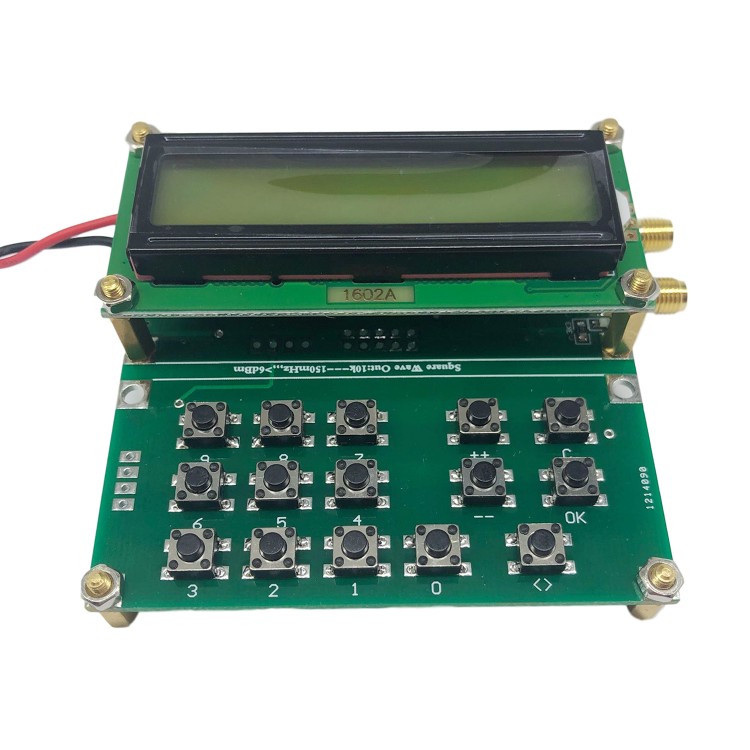
Si 5351-2VFO-150 2-Channel Signal Generator Simple RF Signal Source Output Bandwidth 0.01MHz-150MHz
Download Materials Here (Board diagram, pictures, software, directly compiled MCU source code):
https://pan.baidu.com/s/1C26fPSkqXQFSD3RpJvSWZQ
The board diagram is drawn with AD10; the bottom layer of MCU is compiled with cvavr. If you cannot download, please contact us.
Specifications:
- Power supply voltage: DC 4.5V-5.5V (Attention: This machine does not have a built-in voltage regulator unit, so please not supply power over the voltage range)
- Power supply current: 60mA
- Output bandwidth: 0.01mHz-150mHz
- Scan output step: 1khz, 10khz, 100khz, 1mhz (4 gears)
- Output impedance: 50 ohm
- Product size: 75*75*27MM
- Product weight: 88g
Package Included:
- 1 x Set of Signal Generator
More Details:
- Output Waveform: square wave. The square wave is the simplest function wave. It only needs a simple low-pass filter or band pass to filter out fundamental or double harmonics (sine wave). In addition to digital circuit applications, the output voltage of commonly used phase-locked loop is the feedback voltage obtained by comparing the phase XOR of the VCO frequency (square wave) with the reference clock frequency (square wave) at the same frequency. Square wave is the most commonly used waveform for practical engineering applications and test applications.
- Output VPP: 2.6V
Operations:
Operating keyboard is composed of 15 ppt buttons. There are 10 digital keys from 0 to 9, and "++" and "--" keys are used to adjust frequency, and also generate transmit output behavior. Short press the "++" or "--" button, step will increase or decrease by 1khz when original frequency is output. When you press and hold "++" or "--" button for more than 1 second, a continuous up or down scan mode will appear. To end the scan, just press the "++" "--" button or "ok" button. The "ok" button is the output control key, press it once to transmit, and press it again to stop transmitting. To end the transmitting caused by "++" or "--", you need to press "OK" twice. When it is outputting, ">>" will appear in the upper right corner of the display. The "C" button functions to end the transmission and return the frequency to zero.
There is a channel selection cycle button at the bottom of the LCD screen, which cycles through selection in turn: Power-on default "channel 1 output", "channel 2 output", "two channels output at the same time".
Step "<>" key is used for continuous addition and continuous subtraction scan mode for easy adjustment. Cycle selection of steps "1K", "10K", "100K", "1mhz". There will be a "<1k>" stepping instruction by default in the first line of LCD1602 when it is powered on. Press "<>" button and there will be 4 stepping states that can be selected cyclically.