| Quantity | 3+ units | 10+ units | 30+ units | 50+ units | More |
|---|---|---|---|---|---|
| Price /Unit | $27.32 | $26.76 | $25.93 | $24.81 | Contact US |
 PF9800 Digital Power Meter Smart Power Meter – Display Voltage, Current, Power & Power Factor
$143.81
PF9800 Digital Power Meter Smart Power Meter – Display Voltage, Current, Power & Power Factor
$143.81
 MASTECH MS5902-TF (US) MS5902TF Circuit Breaker Finder Socket Tester w/ Work Light for GFCI Testing
$39.03
MASTECH MS5902-TF (US) MS5902TF Circuit Breaker Finder Socket Tester w/ Work Light for GFCI Testing
$39.03
 MASTECH MS5902-TD (EU) Circuit Breaker Finder Socket Tester Transmitter Receiver with Work Light
$39.03
MASTECH MS5902-TD (EU) Circuit Breaker Finder Socket Tester Transmitter Receiver with Work Light
$39.03
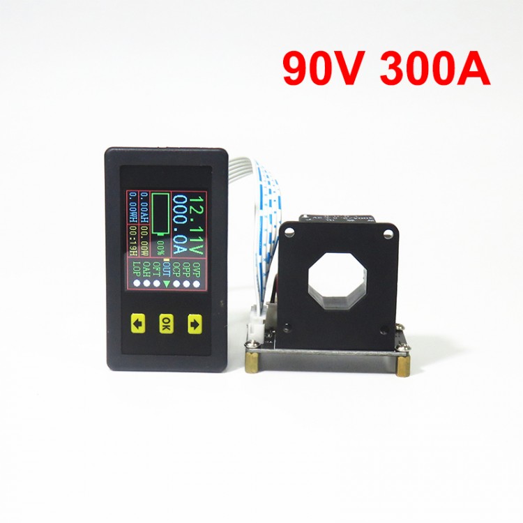
VAC9030H 90V 300A Coulometer Voltage Current Capacity Meter Bidirectional Tester with 1.8" Color LCD
FAQ:
1. Do I need an extension cable?
The meter is connected by a 12cm/4.7" 6P cable by default. If you need our 2m/6.6ft extension cable to extend the distance between the meter display and the measuring board, please contact us.
2. How to set battery capacity, fill up or reset battery capacity?
First, press Down button to move the yellow cursor to the position of OAH, long press the OK key to enter the parameter setting interface. Press Up and Down buttons to increase or decrease the parameter, click the OK key after the setting is completed. And jump out of the parameter setting interface, the yellow cursor is at the position of LOP. Press the Down button when the yellow cursor disappears, then press the OK button once to fill up the battery, press the OK button again to clear the battery, and alternately fill and clear.
3.With multiple protections, such as over-voltage, over-current, over-power, time limit and overcharge protections. It needs to be used with a relay.
Scope of Application:
Monitoring battery charging and discharging of electric vehicles, cars, photovoltaic system power, etc. When it is used for the first time, the no-load current needs to be cleared.
Description:
It is a voltmeter and ammeter capable of measuring various physical quantities such as voltage, current, charge and discharge capacity, time, and power. It can realize various protections such as over-voltage protection, under-voltage protection, over-current protection, overcharge capacity protection and time limit protection by setting parameters. Its user-friendly color LCD displays the measured data, and the display information is comprehensive.
This instrument uses a Hall sensor to detect current. Convenient and simple to use. It is ideal for applications that require monitoring of output voltage and current, as well as charging and discharging batteries.
Features:
1. Two-way detection current. Can be used to detect charging and discharging. It can automatically identify and detect bidirectional current without changing the wiring direction.
2. Power-off memory function. After power failure, it can memorize the AH value before power failure, which is convenient for observation and measurement.
3. Time and AH value clearing function, not affecting the next measurement.
4. The AH value can be filled up without affecting the direct discharge measurement.
5. It can display voltage, current, charging capacity AH value, WH value, time and power at the same time.
6. With output shutdown function key. The output can be turned on or off (relay required).
7. With over-voltage, over-current, over-power, time limit, overcharge and other protection functions.
8. Online calibration is convenient for customers to correct errors in time.
9. You can manually turn off its LCD screen. It can also be turned off automatically one minute after reaching the minimum value. Please consult customer service if you need a LCD screen lit up all the time.
10. Detect current through the Hall sensor, and pass the wire through which the current passes through the sensor hole. It can detect the current in forward and reverse directions, which is safe and convenient for application.
Package Included:
- 1 x Voltage Current Tester
- 1 x Hall Sensor
- 1 x Cable
Note:
- If a 2m/6.6ft extension cable and
RS485 communication function are needed, please contact us to pay for
extra costs. Thank you!
- Battery, relay and other items pictured are not included, for demonstration purposes only. Thank you for your understanding!
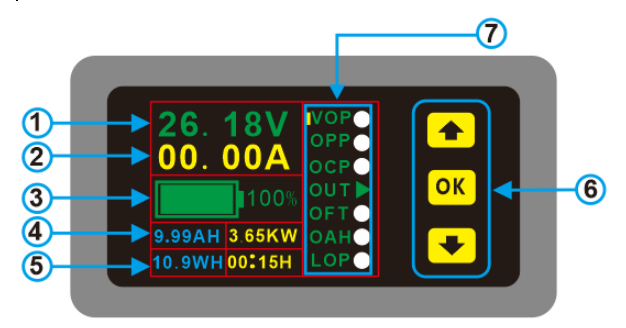
① Voltage
② Current
③ Capacity percentage and progress bar
④ AH (blue) and power (yellow)
⑤ WH (blue) and time (yellow)
⑥ Buttons
⑦ Menu to choose protections

Wiring:
The
circuit diagram below shows the circuit in discharge mode. When it is
charging, you only need to replace the load with a charger without
changing the circuit. The current direction enters from the front of the
transformer, and the current is negative, that is, the remaining power
of the instrument decreases; otherwise, the current is positive, and the
remaining power increases.
1. Figure 1 shows the wiring mode of the power supply without the relay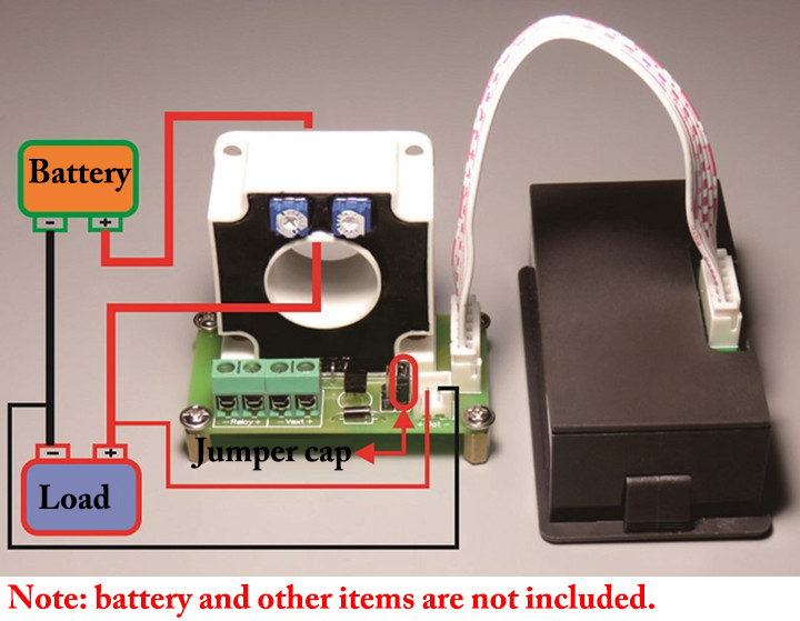
When
in use, the positive and negative poles of the battery correspond to
the positive and negative poles of the "BAT" on the expansion board
respectively. Make sure the wiring is in the correct direction. Pass one
of the positive or negative wires from the battery to the load through
the round hole of the Hall transformer, then connect the jumper cap to
J4, and finally plug the positive and negative terminals of the battery
into the "BAT" on the expansion board and then power on.
2. Figure 2 shows the wiring mode of independent power supply without relay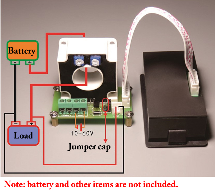
When
in use, the positive and negative poles of the battery should
correspond to the positive and negative poles of the "BAT" on the
expansion board. Be careful not to reverse it. First, pass one of the
positive or negative wires from the battery to the load through the hole
of the Hall transformer, and then connect the jumper cap to J3.
Finally, insert the terminals of the positive and negative poles of the
battery into the "BAT" on the expansion board. Connect to Vext when
externally powered. Pay attention to the positive and negative external
power supply voltage range of 10-60V, do not connect wrongly and
reversely.
3. Figure 3 shows the wiring mode of the independent power supply with relay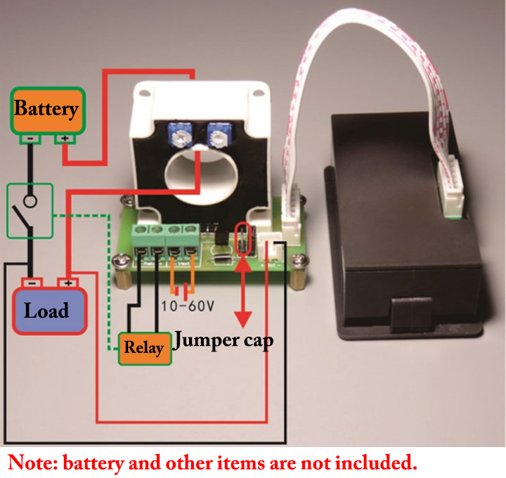
In
use, battery wiring should correspond to the positive and negative
poles of "BAT", and do not reverse it. First, pass one of the positive
or negative wires from the battery to the load through the round hole of
the Hall transformer, then press the jumper cap at J3, and then connect
the relay. Finally, insert the terminals of the positive and negative
poles of the battery into the "BAT" on the expansion board, and connect
the external power supply to "Vext". The external power supply voltage
range is 10-60V, be careful not to connect it wrongly. (Note: The
independent power supply matches the relay voltage)