| Quantity | 3+ units | 10+ units | 30+ units | 50+ units | More |
|---|---|---|---|---|---|
| Price /Unit | $12.24 | $11.99 | $11.62 | $11.12 | Contact US |
 FUZRR ES3000P Multifunctional Micro-controller 3-Wire Ground Resistance Tester 0-20Kohms High Precision Earth Resistance Tester
$275.47
FUZRR ES3000P Multifunctional Micro-controller 3-Wire Ground Resistance Tester 0-20Kohms High Precision Earth Resistance Tester
$275.47
 150W Multifunctional Bluetooth Battery Capacity Tester CC/CR/CP/CV/PT/BRT Intelligent DC Programmable Electronic Load
$59.21
150W Multifunctional Bluetooth Battery Capacity Tester CC/CR/CP/CV/PT/BRT Intelligent DC Programmable Electronic Load
$59.21
 FUZRR ES3090E 220A Loop Resistance Tester Micro-ohmmeter for High Voltage Switch Contact Resistance Measurement
$1,466.23
FUZRR ES3090E 220A Loop Resistance Tester Micro-ohmmeter for High Voltage Switch Contact Resistance Measurement
$1,466.23
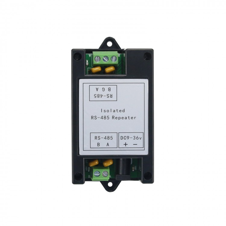
Wi485 Industrial Grade Isolated RS485 Repeater Photoelectric Isolator Amplifier Distance Extender
Description:
Isolated RS485 repeater is a high-performance industrial-grade RS485 signal amplifier and extender. It can automatically sense the direction of data flow and the communication baud rate, without any control nor handshaking signal, ensuring full transparent data transmission. The equipment power supply and communication signal are completely isolated, with surge protection, electrostatic protection and other measures. It features long transmission distance, high speed, stable and reliable performance. It is widely used in attendance machines, IC card toll collection systems, automated control, access control systems, parking lots, canteen sales systems, and highway toll collection systems.
Features:
1. Industrial-grade design, complete communication isolation, stable and reliable performance, and transmission rate up to 115.2Kbps;
2. Built-in high-quality DC/DC isolated power supply module to achieve electrical isolation between ports;
3. Support multi-machine communication, up to 128 nodes can be connected, and the longest transmission distance is 1200 meters;
4. Data flow automatic control technology, automatically distinguish and control data transmission direction;
5. Multiple protections: plus or minus 15KV ESD protection, 600W dual-channel TVS protection, 2.5KV communication isolation;
6. Power supply has a wide range of 9-36VDC, and has reverse connection protection.
Electrical Parameters:
RS485 equipment is suitable for long-term stable operation under the recommended value. The equipment will not be damaged when working under the limit value, but may cause performance degradation. Do not exceed the limit value range at any time, otherwise it may cause equipment damage!
- Working Voltage: Recommended value (typical value) DC 9-36V; limit value DC 9-36V.
- Rated Power: Recommended value (typical value) 0.36W (9V/35mA; 12V/27mA; 24V/15mA); limit value 0.5W.
- Working Temperature: Recommended value (typical value) -30℃ to 70℃; limit value -40℃ to 80℃.
- Responsible Capacity: Recommended value (typical value) 1-128 nodes; limit value 128 nodes.
- Communication Distance: Recommended value (typical value) 0-1200 meters; limit value 1200 meters.
- Communication Rate: Recommended value (typical value) 300-500K bps; limit value 500Kbps.
Wiring Notes:
1. 485 communication line must use shielded twisted pair, it is better to prepare multiple strands for spare, the total length does not exceed 1200 meters.
2. The wiring should be as far away as possible from high-voltage wires, not parallel to power lines, and not to be bundled together.
3. 485 bus must have a hand-in-hand bus structure, and resolutely eliminate star connections and bifurcation connections.
4. If more than 30 controllers or the line length is greater than 500 meters, 485 repeaters must be used.
5. AC-powered equipment and chassis must be well grounded.
6. Connect the GND ground of all 485 devices with shielded wires.
Requirements for Wire Selection Using RS-485 Bus for Communication:
- Use 2-core shielded twisted pair cable
- Copper, wire diameter 0.5~0.75 square millimeter
- Impedance 38~88 ohm/km
- Capacitive resistance 30~50 nanofarad/km
- 2-core shielded twisted-pair cable with a twisting distance of 20 mm (if the distance of the cable is not more than 500 meters, the standard of the cable can be appropriately reduced, but it must be a twisted pair)
Bus Restrictions:
It is composed of two or more devices that have physical connections with each other. A maximum of 128 devices are allowed on the bus. Without repeaters, the length of the bus is no more than 1200 meters. The system bus should not be branched. If branching is inevitable, the following requirements must be met:
1. The branch length is not more than 10 meters; the total length of the bus is not more than 800 meters; the total number of devices on the branch line must not exceed 50pcs.
2. All communication signal lines should be kept away from interference sources as far as possible. The signal lines should go through weak electricity wells. They should not run in parallel with strong current (such as 220V residential power supply) or radio frequency signal lines (such as CATV, large signal audio lines). If you run the lines in parallel, the distance should be greater than 0.5 meters.
3.The connections of all circuits must be connected by welding or screw clamping, and be waterproof and moisture-proof. For example, the butt joints can be welded tightly with waterproof tape or sealed with epoxy resin.
Signal Common Ground:
1. All devices on the same network segment must have a unified signal ground to avoid common mode interference.
2. For centralized power supply, directly connect the DC negative poles of all power supplies on the same network segment (including the self-contained power supplies of communication equipment) to form a common signal ground. At this time, the signal ground is the DC power supply ground.
3. When a single home supplies power independently, connect the ground (black wire) pins of all bus devices on the same network segment together to form a common signal ground.
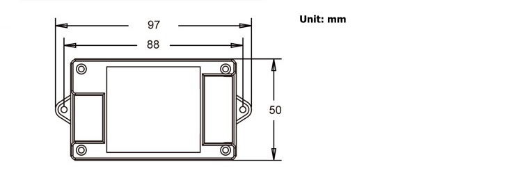
Wiring Diagram:
- Size: 97*50*31 mm; Weight: 66G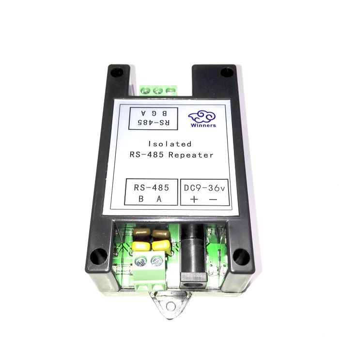
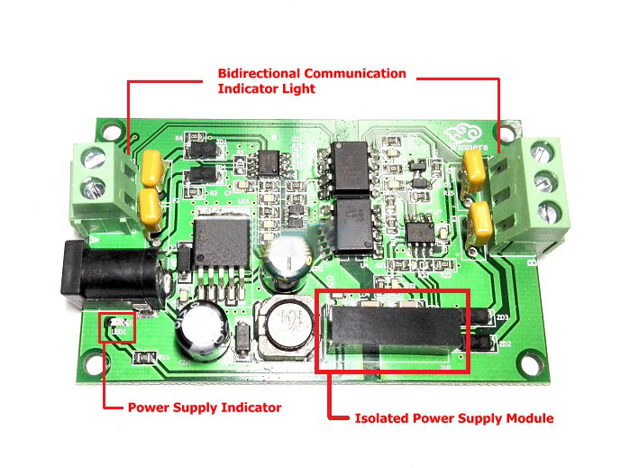
Indicator Lights:
- PWR: Red power supply indicator. It is always on when it is powered on.
- COM: Green data indicator. It flashes when there is data on the bus.
Terminal Definition:
1.DC 9V: Power supply port.
2.G: Isolated RS-485 terminal ground. Can be connected to earth or shielded wire.
3.A: RS-485 signal input/output +.
4.B: RS-485 signal input/output -.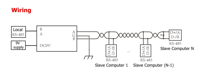
Several Debugging Methods are Recommended:
First of all, make sure that the equipment wiring is correct and strictly in compliance with the specifications:
1. Common Ground Method: Connect the GND ground of all 485 devices with one wire or shielded wire. This can avoid the potential difference between all devices that affects communication.
2. Intermediate Segment Disconnection Method: By disconnecting from the middle, check whether the equipment is overloaded, the communication distance is too long, or the damage of a certain device affects the entire communication line.
3. Separate Wire Drawing Method: Simply pull a wire to the device temporarily and separately. This can be used to rule out whether the wiring caused the communication failure.
4. Replace Converter Method: Carry several converters with you. This can rule out whether the quality of converters is affecting the communication quality.
5. Notebook Computer Debugging Method: First ensure that the notebook computer you carry is a normal communication device, and replace the client computer to communicate. If communication is enabled, it indicates that the serial port of the client's computer may be damaged.


")
![GECON RTU-308E DAQ Data Acquisition IO Module 8AI + 8DI + 12DO [RS485 + RS232] Modbus RTU](https://www.thanksbuyer.com/image/cache/data/202306/78370/1686964025-3-200x200.jpg "GECON RTU-308E DAQ Data Acquisition IO Module 8AI + 8DI + 12DO [RS485 + RS232] Modbus RTU")
![RTU-318F DAQ Data Acquisition IO Module Industrial Automation 4PT + 4AI + 4AO + 8DI + 6DO [RS485]](https://www.thanksbuyer.com/image/cache/data/202209/78371/1664359291-1-200x200.jpg "RTU-318F DAQ Data Acquisition IO Module Industrial Automation 4PT + 4AI + 4AO + 8DI + 6DO [RS485]")
![GECON RTU-308E DAQ Data Acquisition IO Module 8AI + 8DI + 12DO [RS485] Modbus RTU](https://www.thanksbuyer.com/image/cache/data/202407/78369/1721610074-4-200x200.jpg "GECON RTU-308E DAQ Data Acquisition IO Module 8AI + 8DI + 12DO [RS485] Modbus RTU")
