| Quantity | 3+ units | 10+ units | 30+ units | 50+ units | More |
|---|---|---|---|---|---|
| Price /Unit | $16.55 | $16.21 | $15.71 | $15.03 | Contact US |
 SUP-C703S Signal Generator & Process Calibrator – mA, V, Ω, RTD, Thermocouple Output & Measurement
$156.44
SUP-C703S Signal Generator & Process Calibrator – mA, V, Ω, RTD, Thermocouple Output & Measurement
$156.44
 6000A 20µH Air Core Inductor for Dual Pulse Testing and High-Performance Electrical Experiments
$86.76
6000A 20µH Air Core Inductor for Dual Pulse Testing and High-Performance Electrical Experiments
$86.76
 DP8000 Max IGBT Pulse Generator with Internally Integrated IGBT Driver (Air Core Inductor Included)
$384.16
DP8000 Max IGBT Pulse Generator with Internally Integrated IGBT Driver (Air Core Inductor Included)
$384.16
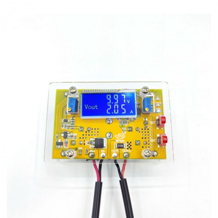
Winners WD3610 10A DC Adjustable Power Supply Module Step Down Module Buck Converter with LCD Screen
Read before Purchasing:
Please read the introduction of the product carefully. Before shipment, the product has passed tests. Please look at the wiring method first, and then power on to test and solder. Due to incorrect wire, misoperation or DIY modification, the product is not covered by the warranty.
Calibration Method:
The module comes with a calibration function. Only need to calibrate once! The default is that the product has been calibrated before delivery. When receiving the item, if its display is inaccurate, it can be calibrated in the following way!
Voltage Calibration:
In the case of power failure, press and hold the Setting Button, power on, and enter the voltage calibration mode. At this point, the LCD screen begins to flash. Release the Setting Button, press the Setting Button to increase the voltage, and press the OK Button to decrease the voltage. The calibration voltage is the correct input voltage. For example, if the input voltage is 12.65V, the voltage will be adjusted to 12.65V at that time, and the value will be automatically saved after 2 seconds. Calibration is completed by exiting without power.
Attention:
Some customers said that when they received the module, the output voltage of the item could not be adjusted. This is because the default output voltage is about 20V by default. When you encounter this problem, rotate the ADJ-V potentiometer counterclockwise for more than 10 turns until the voltage changes. And then the voltage can be regulated normally.
Features:
- Upgrade power supply module
- Current accuracy is improved by 10 times
- LCD screen can display voltage and current
- Fine workmanship and quality materials ensure more stable and reliable performance
- Finished power supply and universal power supply
- There are holes for users to add a fan
Module Parameters:
- Input voltage: DC 7V-36V
- Output voltage: DC 2V-32V continuously adjustable (it can only be used as a step-down module.) The input must be greater than the output by 1V)
- Output current: adjustable. The peak value is up to 10A (recommended within 8A.) When 4A or below 60W at room temperature, it supports natural heat dissipation. When exceeding the range, please strengthen the heat dissipation! It is recommended to add a small fan! Constant current requires an output voltage of over 2V to adjust current. The current can only be regulated in a constant current state)
- Output power: up to 150W (recommended for use within 100W. When the voltage difference is large, please reduce the power)
- Operating temperature: -20 to +75°C (While using, pay attention to the temperature of transistor. When the operating temperature is exceeded, please strengthen the heat dissipation)
- Accuracy: 0.01V and 0.01A; three-digit display
- Conversion efficiency: up to 95%
- Short circuit protection: With. Currently set constant current
- Input reverse polarity protection: With
- Output back-flow: With
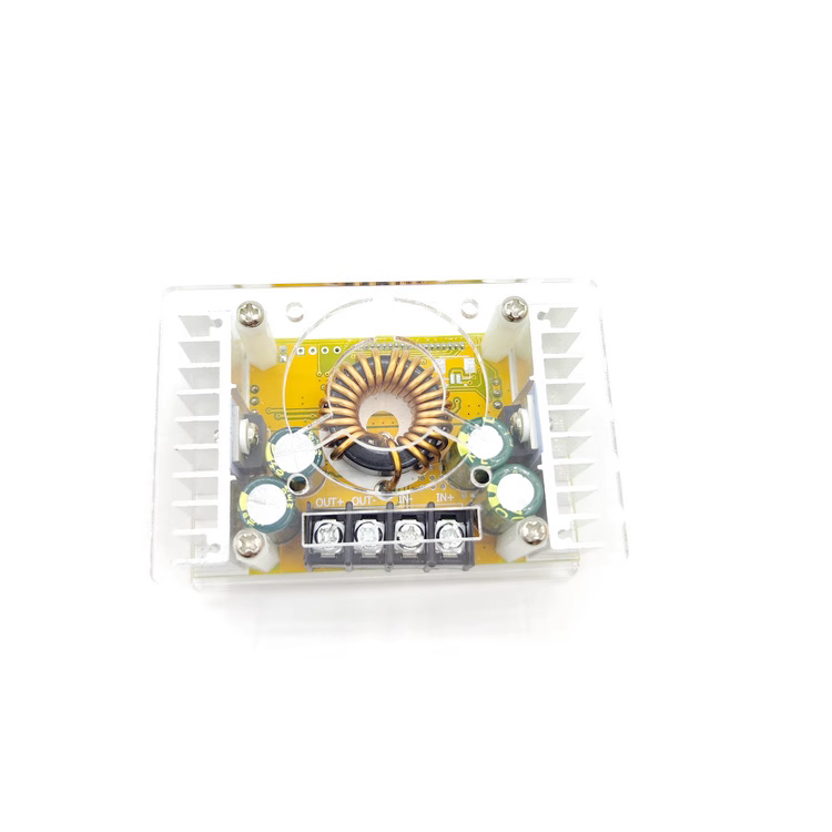
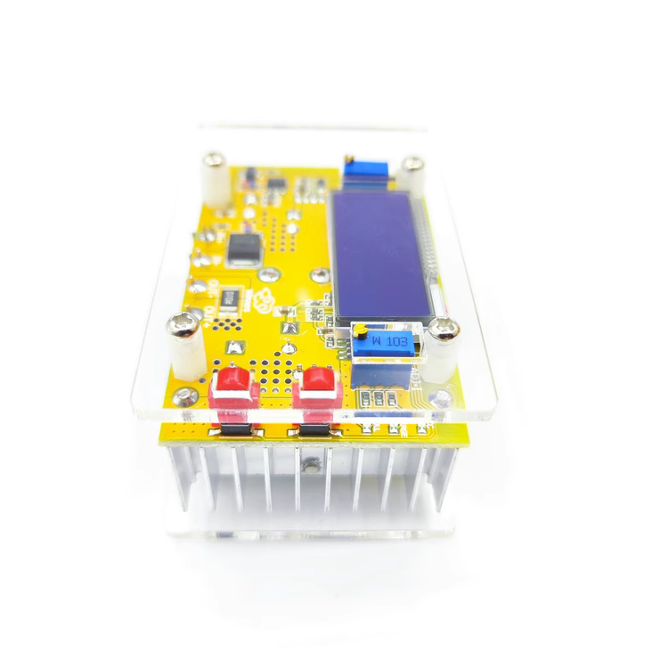
- Installation method: There are two acrylic plates, 8 nylon columns and 8pcs 3m screws. When installing the buttons, the product can be placed reversely, making installation easier
- Wiring method: Via terminals or soldered terminals. IN is the input and OUT is the output
- Module dimensions: 80 x 53 x 35mm/3.1 x 2.1 x 1.4" (LxWxH)
- Weight: 132g/0.3lb
Package Included:
- 1 x Set of power supply module
Note:
- After receiving the module, please assemble the shell by yourselves.
- Battery is not included.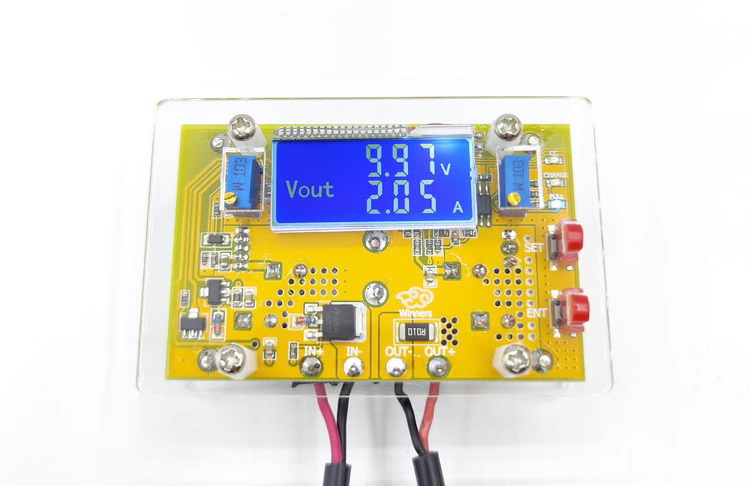
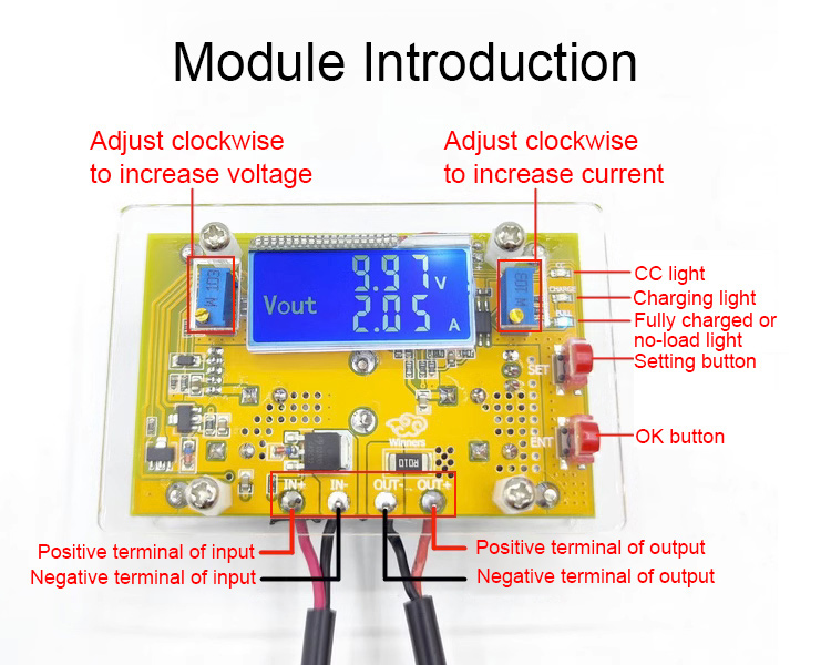
Setting:
The setting button can set display mode. There are three display modes:
1. F-0 mode: display output voltage
2. F-1 mode: display input voltage
3. F-2 mode: display input and output voltage alternately
How to use: Press the Setting Button, the module will cycle through the above three display modes. The corresponding indicator lights will be turned on or off. Press OK Button to save the settings and exit. Press the OK Button individually to turn LCD backlight on and off.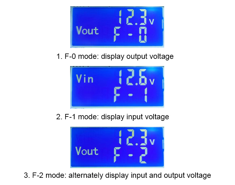
Application:
When the actual load output current is greater than the set current, the module will be in constant current mode. When the output voltage is above 2V, constant current mode will take effect.
1. Used as a normal buck module with over-current protection
How to use:
(1) Under no-load conditions, adjust the "constant voltage potentiometer ADJ-V" so that the output voltage can reach your desired voltage;
(2) Short-circuit the output end of the module (find a thick wire or tweezer to short-circuit the output end. Note: Do not adjust the voltage when it is short-connected. At this time, adjust the "constant current potentiometer ADJ-I" to make the displayed current reach the preset over-current protection value; or connect a load to regulate the current (For example, if the current displayed by the on-board ammeter is 4A, then the maximum current of the module is limited to 4A. When the current reaches 4A, red CC indicator light will be turned on).
(3) Connect a load and the module will work.
2. Used as a battery charger
How to use:
(1) Determine the floating charge voltage and charging current of battery (if the lithium battery parameter is 3.7V/2200mAh, then the floating charge voltage is 4.2V, and the maximum charging current is 1C, that is, 2200mA)
(2) Under no-load conditions, adjust the "constant voltage potentiometer ADJ-V" to make the output voltage reach the floating charge voltage;
(3) Short-circuit the output end of the module (find a thick wire or tweezer to short-circuit the output end. Note: Do not adjust the voltage when it is shorted. At this time, adjust the "constant current potentiometer ADJ-I" to make the displayed current reach the preset charging current; or connect a load to regulate the current.
(4) The current of indicator light change defaults to 0.1 times the charging current. (During battery charging, the current is gradually reduced, and gradually changes from constant current charging to constant voltage charging. For example, the charging current is set to 1A. When the charging current is less than 0.1A, yellow charging light will be turned off. Blue fully charged light will be turned on when the battery is fully charged.)
(5) Connect a battery and charge.
3. Used as a constant current LED driver module
(1) Determine the working current and maximum working voltage you need to drive the LED;
(2) Under no-load conditions, adjust the "constant voltage potentiometer ADJ-V" to make the output voltage reach the LED working voltage;
(3) Short-circuit the output end of the module (find a thick wire or tweezer to short-circuit the output end. Attention: Do not adjust the voltage when it is short-circuited). At this time, adjust the "constant current potentiometer ADJ-I" to make the displayed current reach the preset LED working current; or connect a load to regulate the current.
(4) Connect the LED and test running.


")