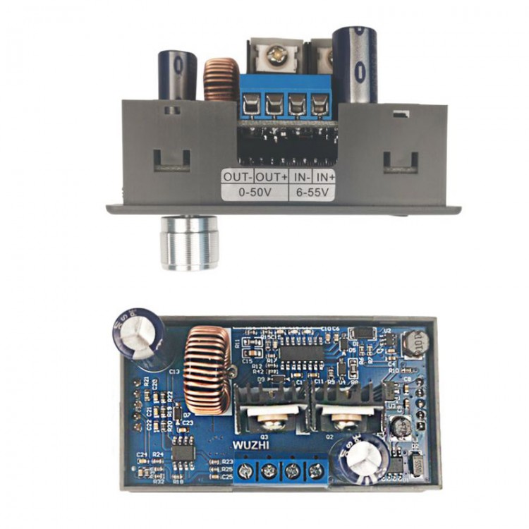
50V 5A CNC Buck Converter Adjustable Step-Down Power Supply Module DC Voltage Regulator LCD Display
Specification:
Model: WZ5005L
Display: LCD display
Input voltage range: 6-55.00V
Input voltage resolution: 0.01V
Output voltage range: 0-50.00V
Output voltage resolution: 0.01V
Output current range: 0-5.000A
Output current resolution: 0.001A
Output power range: 0-250.0W
Input voltage accuracy: ±(1%+5 bits)
Output voltage accuracy: ±(0.3%+5 bits)
Output current accuracy: ±(0.5%+5 bits)
Typical output ripple: 150mV peak
Normal working temperature range: -10℃~40℃
Capacity measurement range: 0-99.99AH
Statistical error of capacity energy: ±2%
Statistical time range: 0-100 hours
Buck working mode: differential pressure>0.05%+1V
Weight with package: about 73g
Product size: 79×43X42mm
Soft start: yes
Features:
1. LCD can display input/output voltage, output current/output power/output capacity/output time.
2. CNC adjustment, precise and fast, step-down output, output voltage 0-50.00V arbitrary adjustment, limit current 0-5.000A arbitrary adjustment.
3. Input terminal anti-reverse protection, will not burn when reverse connection.
4. Not burn when the output flows flow backward.
5. The module can be set to open/close by default.
6. With a variety of software protection mechanisms, and the protection threshold can be adjusted. When the working parameters of the module exceed the protection threshold, the output is automatically turned off.
7. Adopt synchronous rectification technology, the conversion efficiency is high: the efficiency is more than 90%.
8. Equipped with heat sink.
Protection Mechanism:
-Input anti-reverse connection
-Input undervoltage protection (5.8-50V adjustable, default 5.8V)
-Output overvoltage protection (0-51.00V adjustable, default 51V)
-Output overcurrent protection (0 -5.100A adjustable, default 5.1A)
-Output over power protection (0-260W adjustable, default 260W)
-Time-out protection (adjustable from 0-100h, off by default)
-Over-capacity protection (0 -99.99Ah adjustable, off by default)
Instructions:
1. Switch display parameters—In the normal interface, short press SW to switch the display on the lower line of the screen, and the display content switches between current A power W capacity Ah time h. Long press the SW button to switch the upper display of the screen and the display content switches between the input voltage IN and the output voltage OUT.
2. Set the output voltage value—Short press the U/I button in the normal interface to enter the set voltage constant current interface. It can be seen that a certain digit of the set output voltage value is flashing, and turn the rotary encoder left and right to adjust the value. Short press the rotary encoder to select which bit to set. After setting, short press the U/I button to return to the normal interface. Or after stopping operation for 10s, it will automatically return to the normal interface.
3. Set the module to be turned on/off by default at power-on—Long press the U/I button in the normal interface to enter the parameter setting interface. You can see the display of OPEN OFF or OPEN ON. OPEN OFF means that the output is turned off by default at power-on, and OPEN ON means that the output is turned on by default at power-on. Long press the rotary encoder to switch between two states. After setting, long press the U/I button to return to the normal interface.
4. Set the protection parameter on-state and threshold—Long press the U/I button in the normal interface to enter the parameter setting interface. Short press the SW button until the protection parameters you want to set appear. LUP—undervoltage protection threshold; OUP—overvoltage protection threshold; OCP—overcurrent protection threshold; OPP—overpower protection threshold; OAP—overcapacity protection threshold; OHP timeout protection threshold. Short press the rotary encoder to select which bit you want to set the protection parameter. Long press the rotary encoder to set the protection parameters on or off (only timeout protection and over capacity protection can be set on/off, other protection parameters are on by default.). Turning the encoder left and right can make the parameters larger and smaller. After setting, long press the U/I button to return to the normal interface.
5. Calibrate voltage and current—Long press the U/I button in the normal interface to enter the parameter setting interface. Short press the SW button until the interface with Zero appears, with Zero+OUT+A symbol, long press the rotary encoder to complete zero calibration. Short press SW button, the parameter interface of CAL appears. The CAL+IN+V symbol is the calibration input voltage interface; the CAL+OUT+V symbol is the calibration output voltage interface; the CAL+OUT+A symbol is the calibration output current interface. The left and right rotary encoders can adjust the parameter size to the value actually measured with a multimeter. After the adjustment is completed, long press the rotary encoder to confirm the adjustment is complete, at this time the parameter value is not flashing. Long press the U/I button to return to the normal interface.
Package List:
1 x Power Supply Module
Note:
1. After the product triggers the protection mechanism, the output is automatically turned off, the LCD displays the protection code, and press any key to exit the protection interface.
2. In order to ensure the accuracy of calibration, calibration can only be started when the calibration voltage is above 12V; calibration can only be started when the calibration current is above 1A.
3. It is forbidden to short - circuit module input IN- and output OUT-, otherwise the constant current function is invalid.
4. Make sure that the power of the power supply is always greater than the power required by the output load!
5. This module is a buck module, the input voltage should be higher than the output voltage, and a certain margin is left. If you want to output at full load, the input voltage should be 55V.
6. The high power of this module will cause serious heat generation. Be careful of burning! Please pay attention to ventilation and heat dissipation when using for a long time with high power!
7. The module has an input undervoltage protection function, the default is about 5.8V (can be set), when it is lower than this value, it will automatically disconnect the output (note that the voltage at the module port is lower than the undervoltage protection threshold, when the input current is larger, don't ignore the partial voltage on the input wire).
 JD-118 +/-3.5dB High Precision Digital Noise Meter 30-130dB Sound Level Meter with 2.17-inch LCD Screen
$25.39
JD-118 +/-3.5dB High Precision Digital Noise Meter 30-130dB Sound Level Meter with 2.17-inch LCD Screen
$25.39
 JD-105 +/-1.5dB High Precision Digital Noise Meter 30-130dB Sound Level Meter with 2.17-inch LCD Screen
$25.39
JD-105 +/-1.5dB High Precision Digital Noise Meter 30-130dB Sound Level Meter with 2.17-inch LCD Screen
$25.39
 JD-861 Digital Handheld Temperature and Humidity Tester Wet Bulb Temperature and Dew Point Temperature Measurement
$22.23
JD-861 Digital Handheld Temperature and Humidity Tester Wet Bulb Temperature and Dew Point Temperature Measurement
$22.23


")


")
