| Quantity | 3+ units | 10+ units | 30+ units | 50+ units | More |
|---|---|---|---|---|---|
| Price /Unit | $123.63 | $121.10 | $117.32 | $112.27 | Contact US |
 SUP-C703S Signal Generator & Process Calibrator – mA, V, Ω, RTD, Thermocouple Output & Measurement
$156.44
SUP-C703S Signal Generator & Process Calibrator – mA, V, Ω, RTD, Thermocouple Output & Measurement
$156.44
 6000A 20µH Air Core Inductor for Dual Pulse Testing and High-Performance Electrical Experiments
$86.76
6000A 20µH Air Core Inductor for Dual Pulse Testing and High-Performance Electrical Experiments
$86.76
 DP8000 Max IGBT Pulse Generator with Internally Integrated IGBT Driver (Air Core Inductor Included)
$384.16
DP8000 Max IGBT Pulse Generator with Internally Integrated IGBT Driver (Air Core Inductor Included)
$384.16
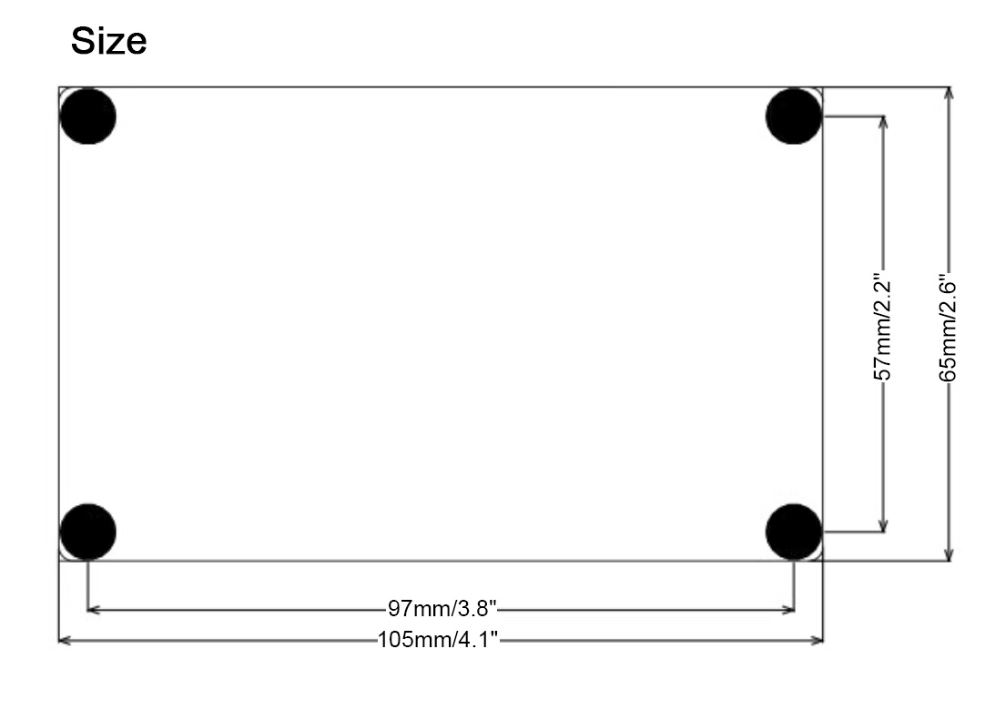
YF-BKT80V30A 10-75V/30A DC-DC Step up down Converter Buck Boost Converter Full Set for Fuel Cells
Read before purchasing:
- Do not use a 3A/5A regulated DC power supply as an input to test the power supply.
- Basic technical knowledge and hands-on ability are highly recommended.
- Users need to modify parameters such as undervoltage protection parameters. We can tell you how to modify it.
-
Certain power supply test and measurement capabilities and equipment
are recommended. Do not test this power supply with a 3A adjustable
regulated power supply used in labs.
- Do not test the current-limiting power supply in CC mode of an electronic load.
-
Output current adjustment range: If the input power is sufficient, and
the output power supply is 20V and a 0.4Ω resistor is connected to
adjust CC potentiometer, the output current can be adjusted to a maximum
of 50A, but cannot be adjusted to the minimum limit value (except 0A).
Tips:
-
The recommended parameters for this module are: input voltage within
75V (limit test at 85V input) and output voltage within 75V. The input
and output currents should be within 32A.
- Input current is up to
40A. It is not recommended to use it for long periods of time at maximum
current, especially in high boost ratio mode, to ensure good heat
dissipation.
- Reverse connection of the positive and negative poles
of the input and output are not allowed, otherwise the related equipment
will be burned.
- Potentiometer lifespan is relatively limited, and frequent adjustment is not recommended.
Application:
- Solar panel or generator power tracking charging
- Fuel cell charging
- The regulated power supply can be adjusted to charge battery
- Applications with limited input power
- For battery to charge battery. Battery is discharged constantly and high-power LED
- A regulated power supply supplies power to devices
- Extend applications for external control voltage and current
Package Included:
- 1 x Set of Buck Boost Converter (power supply board + fan + digital display + heat sink)
Note:
- Battery is not included in the package.
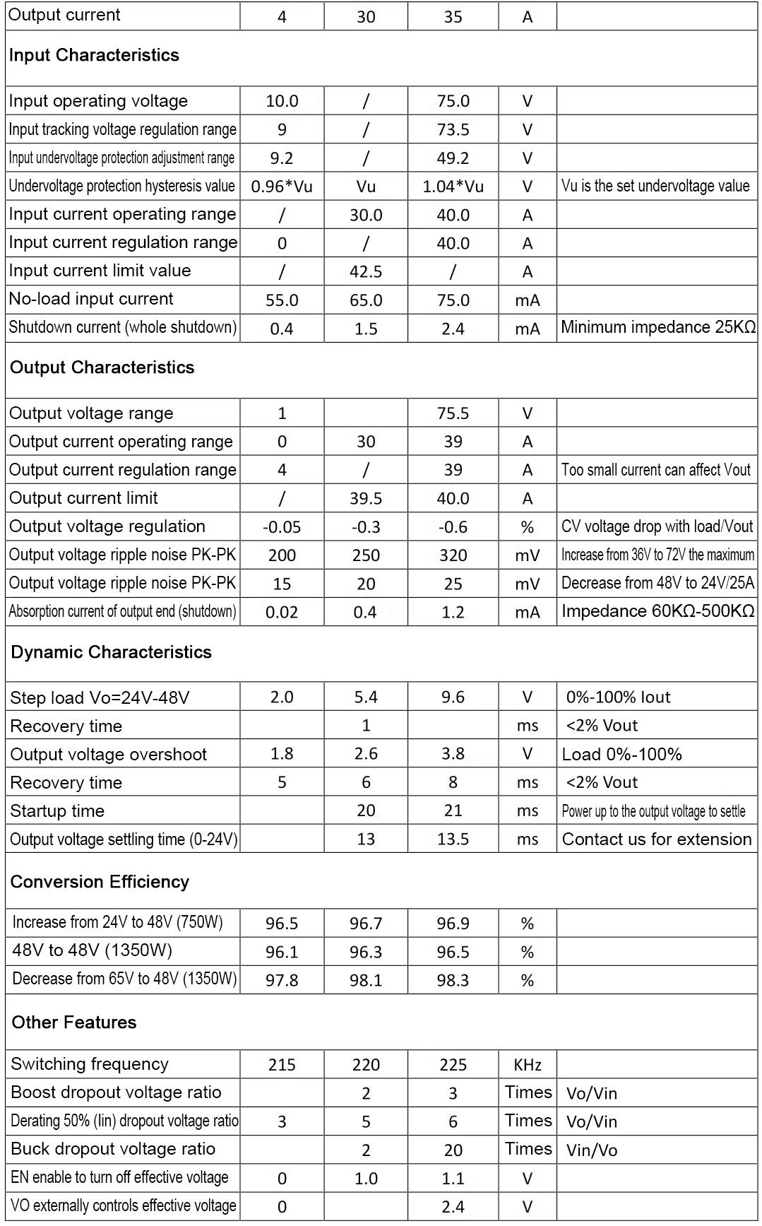
Typical Performance (YF-BKT80V30A):
- Non-isolated four-switch synchronous buck-boost
- Wide input DC10-75V and output DC3-75V
- Peak efficiency ≥ 98%
- Over-current protection
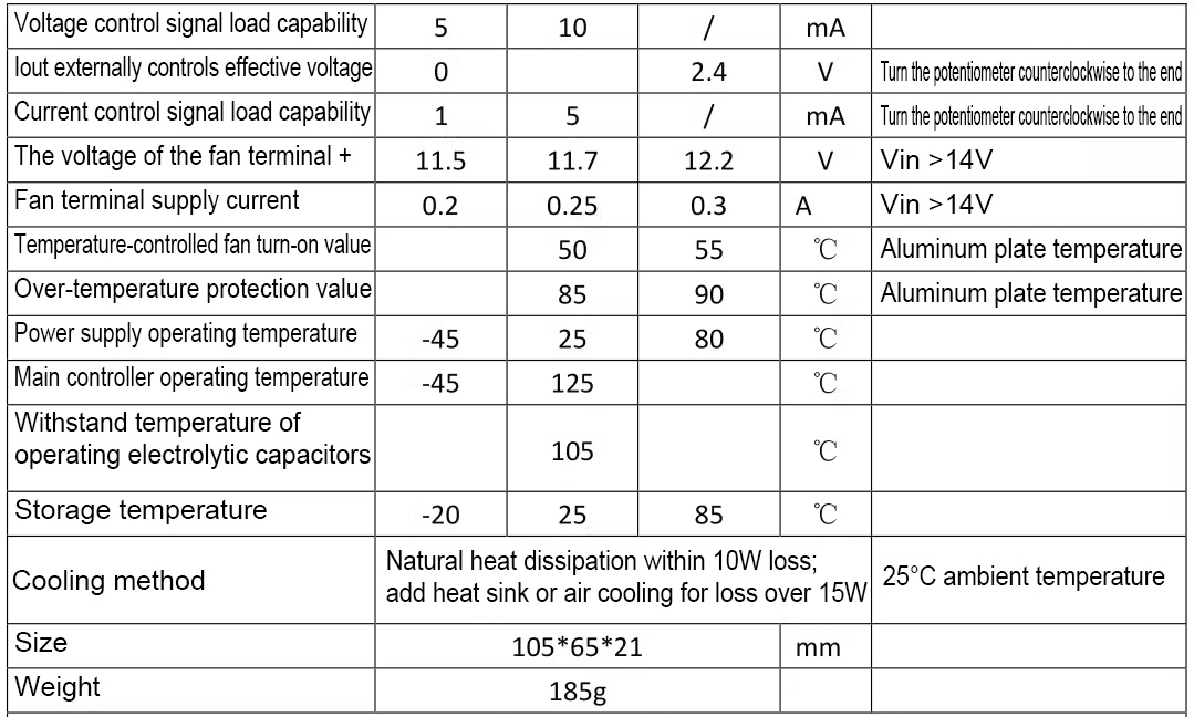
- Over-temperature protection self-recovery
- Remote ON/OFF
- Optional temperature-controlled fan
- Load indication
- Optional output voltage and current display
- Adjustable input voltage and current
- Adjustable output voltage and current
- The output voltage and current are externally controllable
- Input voltage tracking is suitable for battery panels
- Battery charge back-charge protection to 80V
- Low quiescent current, high regulation accuracy, constant frequency operation MEI for easy prediction
- Power can be over 1000W (input and output> 36V)
-
All tests are made at 48V input voltage, resistive load, and room
temperature at 25°C. Parameters are subject to change without notice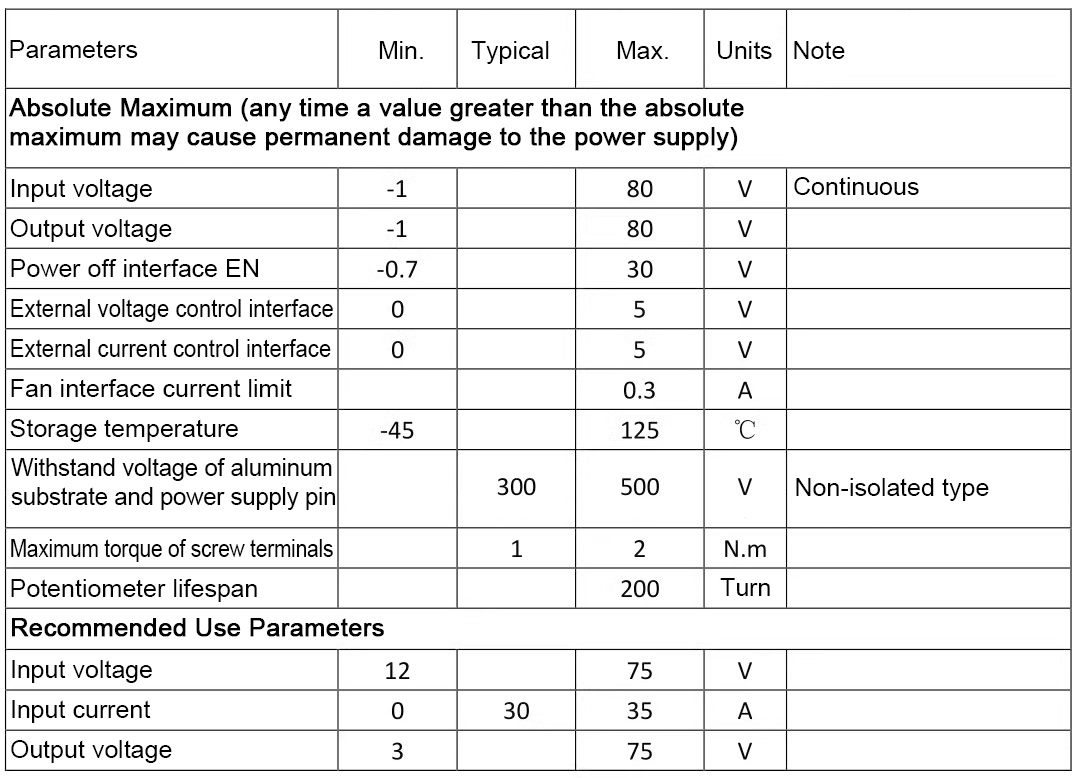
Attention:
1:
Input voltage tracking is suitable for non-constant voltage input such
as battery panels, fan power generation, and receiving end of wireless
energy transmission.
2: Input current regulation is suitable for
adapters, switching power supplies, and other applications that need to
allocate or limit the maximum input current.
3: The ripple current of
the boost output capacitor is large, and the ripple of the buck input
capacitor is large. Thus, LC filter can be added by users.
4: It can
be directly connected to battery for charging. It is recommended to
adjust the output voltage correctly before connecting the target
battery.
5: When the startup time of the input source is long, users
need to adjust the startup time. For example, the AC adaptation output
full-load voltage settling time is 50ms, while the power supply start-up
time is 15ms, which may cause AC to fail to start normally.
6: It is
not recommended to adjust the output current limit to less than 4A,
otherwise the output voltage will be 0.2-2V lower. When it is adjusted
to 0A, there will be no output.
7: For different applications, some parameters may need to be adjusted.


Attention:
1:
When testing this power supply, it must be ensured that the input
source can provide a large enough current (>45A) to ensure that the
power supply does not collapse or even be damaged. If it cannot be
guaranteed, not use it with a large load or test the full function.
2:
The startup time of the input source must be less than the startup time
of this power supply (such as the adapter as input), otherwise it may
not be possible to start with load.
3: The input wire connected to
this power supply shall not be too long (the internal resistance of the
wire shall not be too large), otherwise the power supply may cause
oscillation and abnormality. Over-voltage caused by the long wire pulse
operating current should be avoided to damage the equipment or power
supply.
4: If there is a diode in series with the input source to the
power supply, there should be enough input voltage margin to ensure
that the power supply is not damaged by the over-voltage caused by the
instantaneous on-off.
5: Do not use the CC mode of an electronic load
as the load of this power supply (it must be ensured that the input
power is greater than the output power in any case). It is recommended
to use the CR mode. CC mode draws current, this power supply is current
limited, and in constant current mode, this will cause the power supply
to crash.
6: It is recommended to connect the adjustable output
voltage with a resistive load (dummy load) with small current to ensure
real-time adjustment of the output voltage potentiometer. Otherwise, the
output voltage will change slowly and the regulation will be
inaccurate.
7: Do not use a mains electricity voltage regulator as
input after rectification, because DC is equivalent to connecting to a
power grid and it is easily damaged. Users who have to use it as a last
resort must install an isolation transformer.