| Quantity | 3+ units | 10+ units | 30+ units | 50+ units | More |
|---|---|---|---|---|---|
| Price /Unit | $109.15 | $106.92 | $103.58 | $99.13 | Contact US |
 SUP-C703S Signal Generator & Process Calibrator – mA, V, Ω, RTD, Thermocouple Output & Measurement
$156.44
SUP-C703S Signal Generator & Process Calibrator – mA, V, Ω, RTD, Thermocouple Output & Measurement
$156.44
 6000A 20µH Air Core Inductor for Dual Pulse Testing and High-Performance Electrical Experiments
$86.76
6000A 20µH Air Core Inductor for Dual Pulse Testing and High-Performance Electrical Experiments
$86.76
 DP8000 Max IGBT Pulse Generator with Internally Integrated IGBT Driver (Air Core Inductor Included)
$384.16
DP8000 Max IGBT Pulse Generator with Internally Integrated IGBT Driver (Air Core Inductor Included)
$384.16
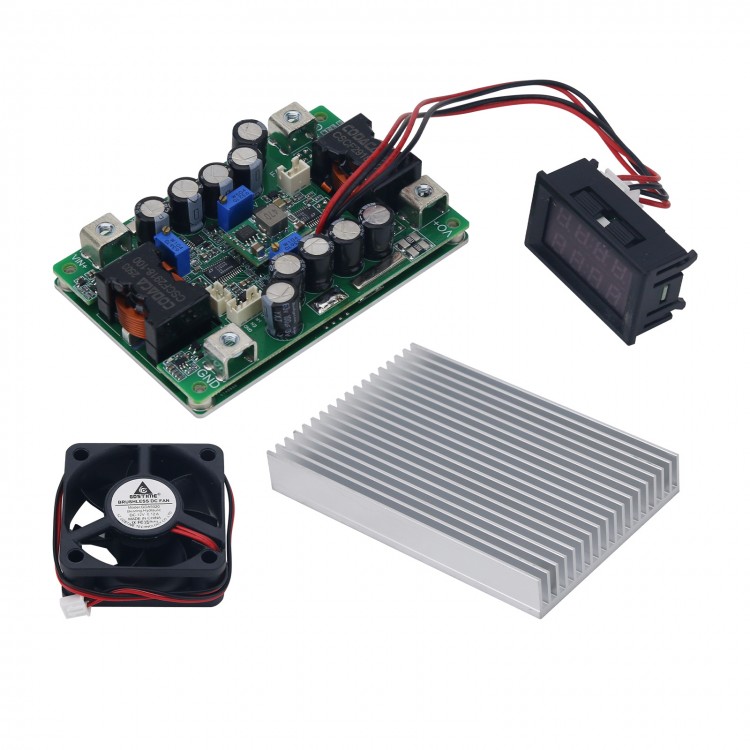
YF-BKT60V50A 50A/12-60V DC Automatic Buck Boost Converter Step up down Converter Full Set CC CV
Read before purchasing:
- Do not use a 3A/5A regulated DC power supply as an input to test the power supply.
- Basic technical knowledge and hands-on ability are highly recommended.
- Users need to modify parameters such as undervoltage protection parameters. We can tell you how to modify it.
-
Certain power supply test and measurement capabilities and equipment
are recommended. Do not test this power supply with a 3A adjustable
regulated power supply used in labs.
- Do not test the current-limiting power supply in CC mode of an electronic load.
-
Output current adjustment range: If the input power is sufficient, and
the output power supply is 20V and a 0.4Ω resistor is connected to
adjust CC potentiometer, the output current can be adjusted to a maximum
of 50A, but cannot be adjusted to the minimum limit value (except 0A).
Features:
- DC-DC step up down power supply with high current
- 2-way master-slave staggered parallel, good current sharing
- Adjustable voltage and current
- Can be paralleled to higher currents, with over-temperature protection
- Input and output within 30V, and 50A is supported
Typical Performance (YF-BKT60V50A):
- Non-isolated four-switch synchronous buck-boost
- Wide input DC9-58V and output DC3-56V
- Peak efficiency> 98.0%
- Over-current protection, short-circuit protection self-recovery
- Remote ON/OFF
- Over-temperature protection, optional temperature-controlled fan
- Constant current indicator light
- Output voltage and current are adjustable and externally controllable
- Input voltage tracking is suitable for fuel cells
- Optional output voltage current display
- Battery charge back-charge protection up to 60V
- Super capacitor zero voltage constant current charging
-
Low quiescent current, high regulation accuracy, constant frequency
operation MEI for easy prediction, selectable low EMI spread spectrum
modulation mode
- Power can be over 1KW (input and output > 24V)
-
All tests are made at 24V input voltage, with resistive load and 25°C
room temperature. Parameters are subject to change without notice


Attention:
1.
The ripple current of the boost output capacitor is large, the ripple
current of the step-down input capacitor is large, and the electrolytic
capacitor can be connected in parallel to reduce the heating of the
capacitor and extend the life.
2. Can be directly connected to a
battery to charge. It is recommended that the output voltage be properly
adjusted before connecting the target battery.
3. The slow start
time is the same as the EN enable control delay time, and the output
slow start time needs to be adjusted when the input source start time is
long. For example, the settling time of the AC adaptation output full
load voltage is 50ms, and the start-up time of this power supply is 2ms,
which may cause AC to fail to start normally with load. It is necessary
to start the AC power supply before starting the DC power supply.
4.
The input voltage regulation function cannot be limited to the case
where the output current is 0, and the minimum limit output current is
2-5A, that is, a battery panel will be offset when the power is low, and
it cannot be adjusted in an ultra-wide range.
5. When the output
constant voltage and constant current switching is critical, there will
be a deviation of 0.5-1V in the constant voltage stage. For example, if
the current limit is set to 20A at no load of 29.4V, the output voltage
will be lower than 28.7V, and the current will be constant 20A (-5%). At
28.8-29.0V, the current may be 18-15A. This can be affected by the
internal resistance of the wire and the internal resistance of the
battery. Constant voltage mode is subject to load regulation.
6. Some parameters may need to be adjusted for different applications.
Package Included:
- 1 x Set of buck boost converter (power supply board + heat sink + fan + auxiliary board + display module)
Note:
- Battery is not included in the package.

Attention:
1.
When testing this power supply, it must be ensured that the input
source can provide a large enough current (>65A) to ensure that the
power supply does not collapse or even be damaged, especially when it
starts with load.
2. The input source startup time must be less than
the startup time of this power supply (e.g. using an adapter as input),
otherwise it may not be possible to start with load.
3. The input
wire connected to this power supply must not be too long (the internal
resistance of the wire must not be too large), otherwise the power
supply may oscillate and be abnormal.
4. If there are diodes in
series with the input source to this power supply, the power supply may
be damaged due to the surge voltage caused by the instantaneous on-off
(line BOOST effect). Long wires should ensure that the input voltage is
below 50V and leave sufficient margin.
5. Do not use the CC mode of
an electronic load as the load of this power supply, it is recommended
to use the CR mode. CC mode draws current, and this power supply is
current limited, and the constant current state will cause this power
supply to crash.
6. It is recommended that adjustable output voltage
be connected to a resistive load (dummy load) with a small current to
ensure real-time adjustment of the output voltage potentiometer.
Otherwise, the output voltage will change slowly and the regulation will
be inaccurate.
7. The current limit value setting should use CR mode
or a battery with electric quantity < 60%. For example, the no-load
voltage is set to 29.4V, and then the current limit value is set to 20A,
the load resistance is 0.88Ω~1.17Ω (29.4*0.6/20A<R<29.4*0.8/20A).
A 1Ω resistor can be used and the potentiometer is adjusted until the
output current is 20A.