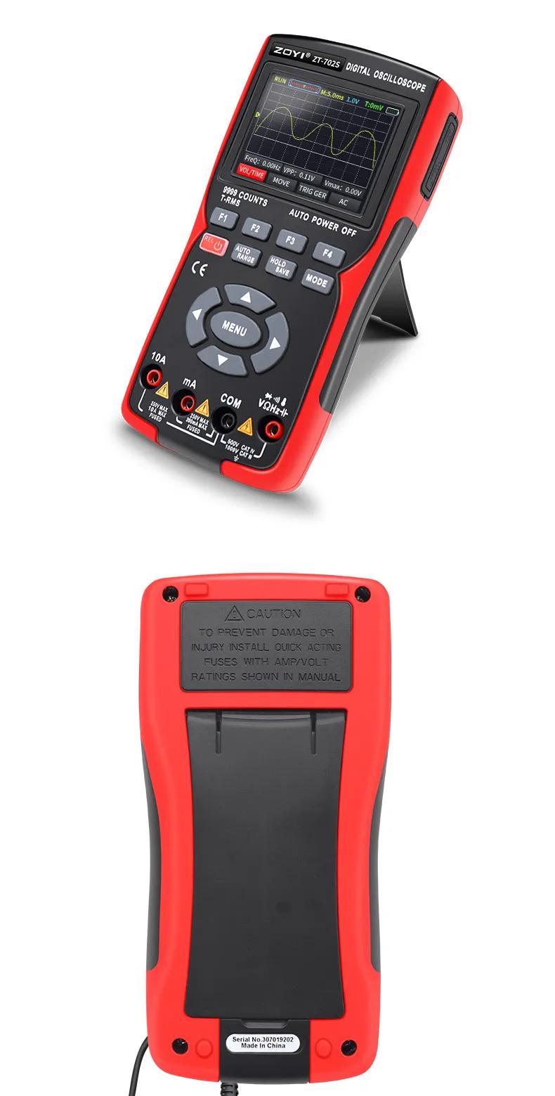
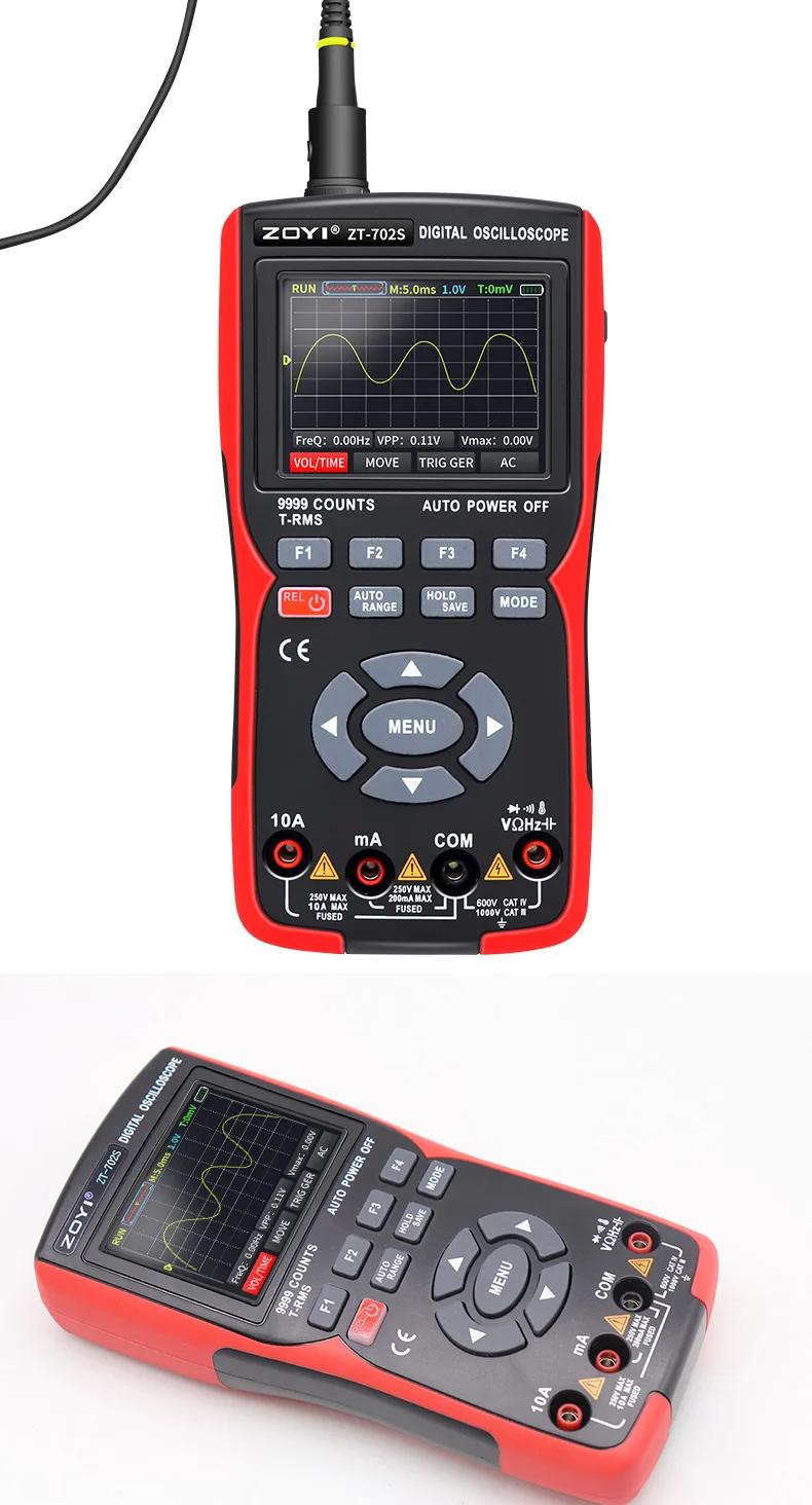
| Quantity | 3+ units | 10+ units | 30+ units | 50+ units | More |
|---|---|---|---|---|---|
| Price /Unit | $65.80 | $64.45 | $62.44 | $59.75 | Contact US |
 FUZRR ES3000P Multifunctional Micro-controller 3-Wire Ground Resistance Tester 0-20Kohms High Precision Earth Resistance Tester
$275.47
FUZRR ES3000P Multifunctional Micro-controller 3-Wire Ground Resistance Tester 0-20Kohms High Precision Earth Resistance Tester
$275.47
 150W Multifunctional Bluetooth Battery Capacity Tester CC/CR/CP/CV/PT/BRT Intelligent DC Programmable Electronic Load
$59.21
150W Multifunctional Bluetooth Battery Capacity Tester CC/CR/CP/CV/PT/BRT Intelligent DC Programmable Electronic Load
$59.21
 FUZRR ES3090E 220A Loop Resistance Tester Micro-ohmmeter for High Voltage Switch Contact Resistance Measurement
$1,466.23
FUZRR ES3090E 220A Loop Resistance Tester Micro-ohmmeter for High Voltage Switch Contact Resistance Measurement
$1,466.23
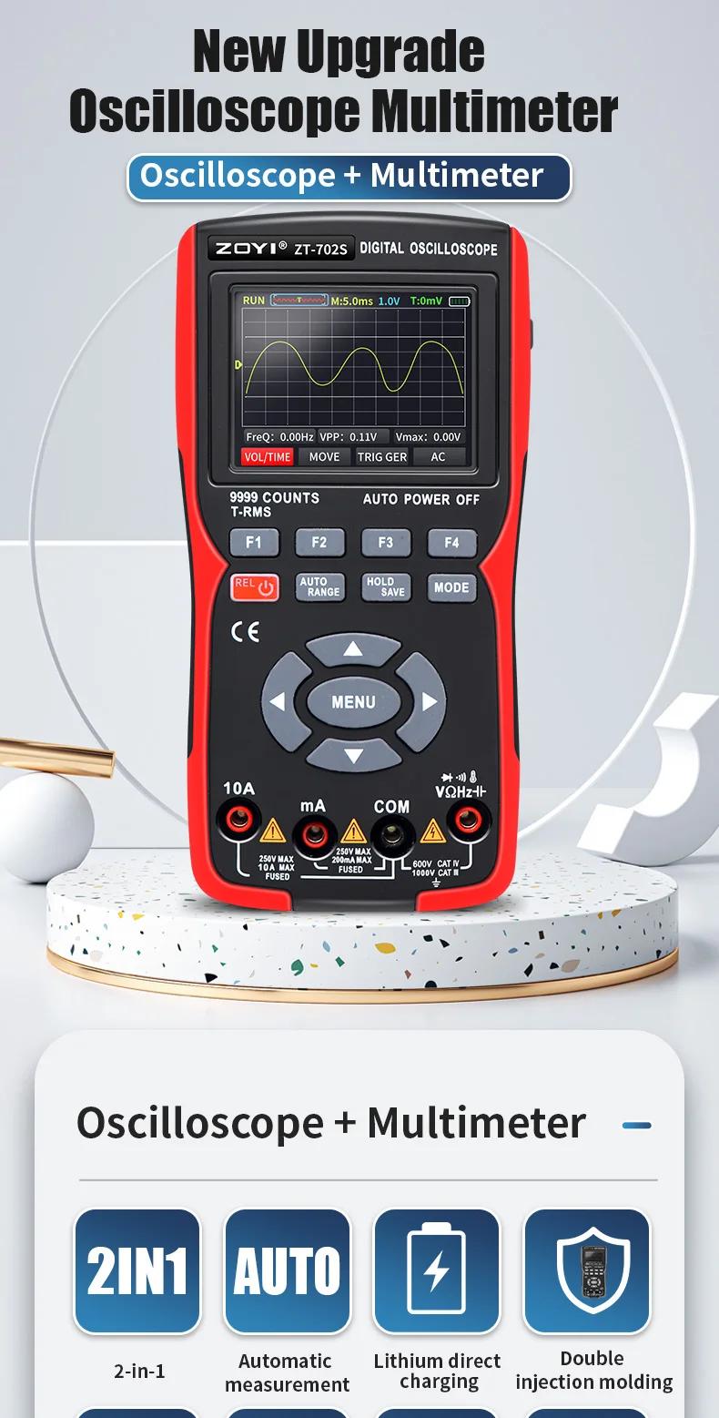
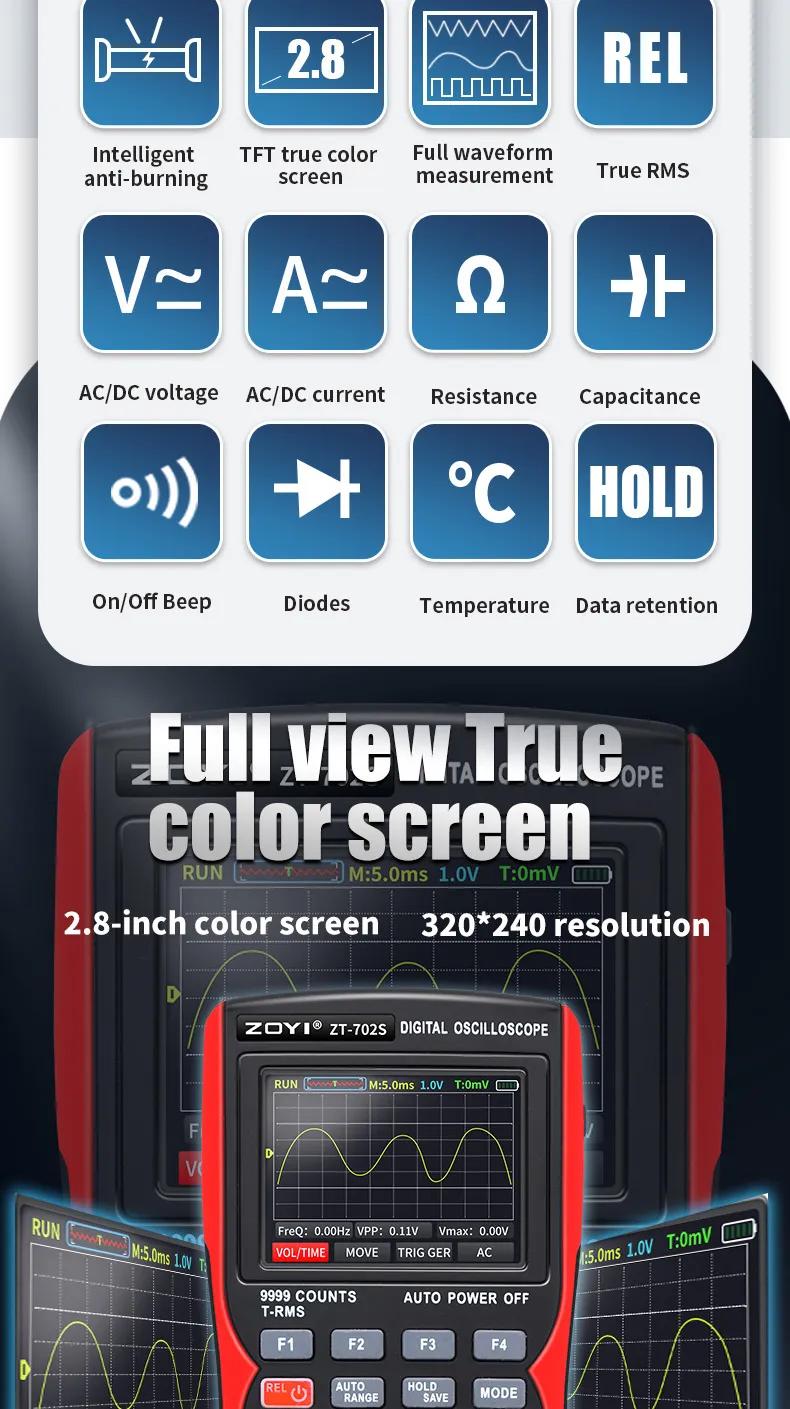
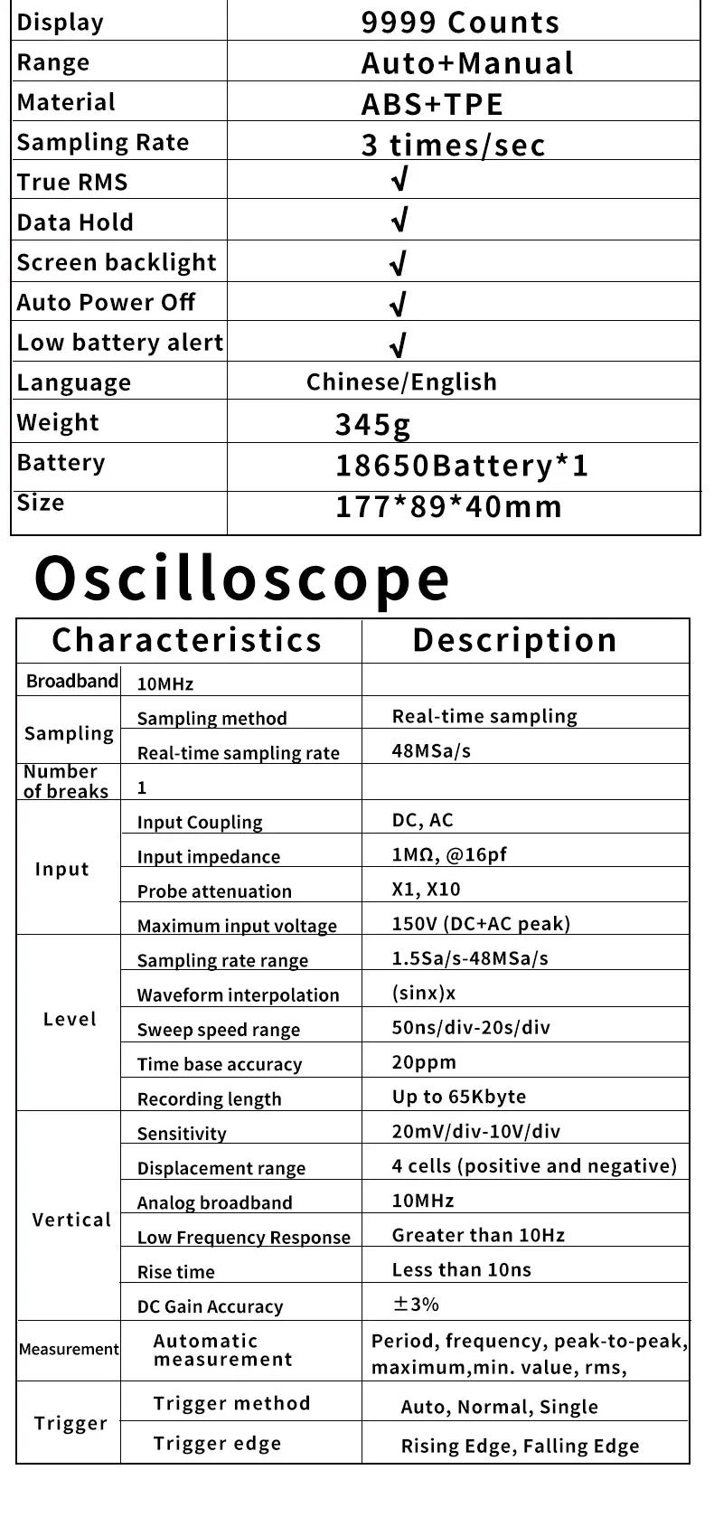
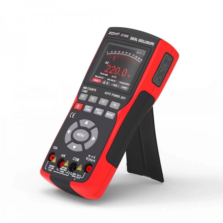
ZT-702S Handheld Multifunctional Digital Oscilloscope Multimeter Automobile Repair Instrument with 2.8-inch Color Screen
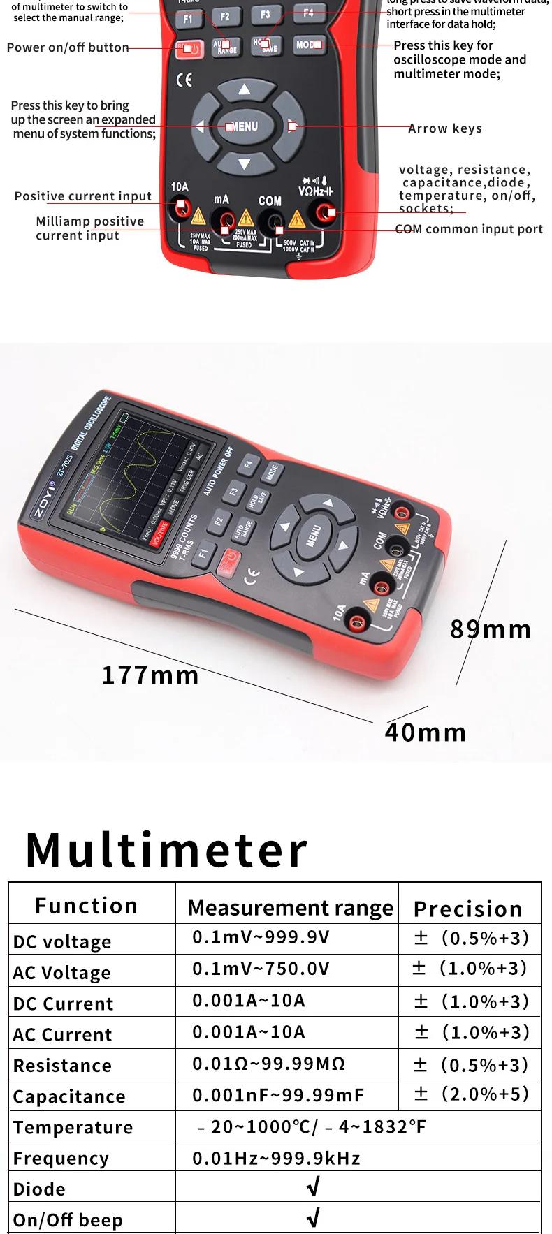
Main Interface Description:
- Operating status display:
RUN: automatic waveform acquisition status
WAIT: normal trigger mode, flashing waiting for trigger signal
T·D: trigger waveform data obtained
STOP: locked the current waveform and stopped collecting
- Time base window: displays the current time base position within the storage depth
- Time base scale: displays the current set horizontal time base scale value
- Voltage scale: displays the current set vertical voltage scale value
- Trigger level: display the current set trigger voltage value
- Battery level: display the current battery level status and charging display
- Horizontal cursor: displays the current triggered horizontal time base position
- Waveform: display the collected waveform status on a large screen
- FerQ: display the frequency value of the collected signal
- Vertical cursor: displays the current triggered vertical voltage position
- VPP: display the voltage peak value of the collected signal
- Vmax: display the maximum voltage value of the collected signal
- (VOL/TIME) Menu: this menu allows you to complete voltage and time base settings:
1. Voltage setting method: press the up button of the panel direction key to increase the voltage amplitude, and press the down button of the panel direction key to decrease the voltage amplitude; Adjustable range: 20mV/div - 10V/div.
2. Time base setting method: press the left button of the panel direction key to enlarge the time base, and press the right button of the panel direction key to reduce the time base; Adjustable range: 50ns/div - 20s/div.
- Waveform Movement (MOVE): press the up and down keys in the panel direction to adjust the up and down positions of the waveform, and press the left and right keys in the panel direction to adjust the left and right positions of the waveform.
- TRIGGER: press the up and down arrow keys on the panel to adjust the position of the trigger cursor.
- Coupling mode (AC DC): press the F4 button on the panel to switch between AC and DC coupling modes.
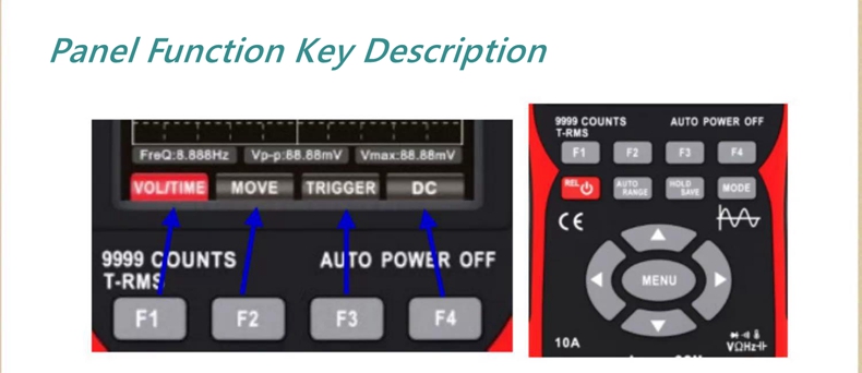
Panel Function Key Description:
- F1-F4 key: corresponding to the function menu displayed on the display screen, select the corresponding function by pressing the key.
- Power button: press and hold for 2S to turn on/off the machine; When in the multimeter mode, briefly press to enter the relative value (REL) measurement.
- AUTO/RANGE key: short press this key under the oscilloscope interface to automatically obtain the measured waveform; Short press to switch to manual range on the multimeter interface.
- HOLD/SAVE key: short press to stop/RUN function on the oscilloscope interface, long press to save the measured waveform data; Short press on the multimeter interface for data hold/cancel hold function.
- MODE key: press this key to switch between oscilloscope mode and multimeter mode.
- Direction keys: the up, down, left, and right direction keys correspond to the use of progressive adjustment of relevant setting parameters, movement of cursor positions, and menu selection of scenes.
- MENU key: press this key to pop up the system function extension menu on the screen.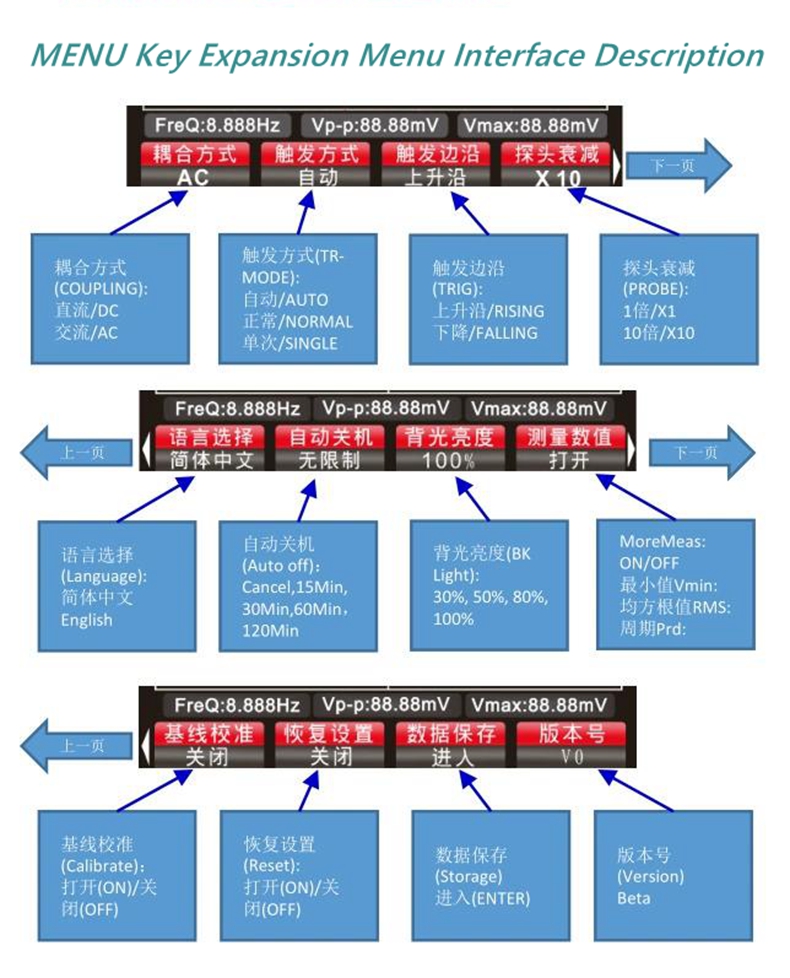
Probe Inspection:
- Security: when using the probe, to avoid electric shock, keep your fingers behind the safety ring on the probe body, and do not touch the metal part at the top of the probe when it is connected to a high-voltage power source; The measured voltage must not exceed the probe specifications.
- Manual probe compensation: When connecting the probe to the oscilloscope for testing for the first time, it is recommended to perform the following checks and compensation. Uncompensated or offset probes can lead to measurement errors. If adjusting the probe compensation, please follow the following steps:
1. After starting the machine, connect the probe to the signal input terminal and input a 4V/1KHz square wave signal.
2. After connecting, press the AUT0 button on the panel to check the waveform display status.
- If necessary, adjust the capacitance on the probe to change the compensation state; The adjustment tool is the accessory adjustment rod attached to the probe or a suitable non-metallic handle adjustment rod. The adjustment method is shown in the following figure: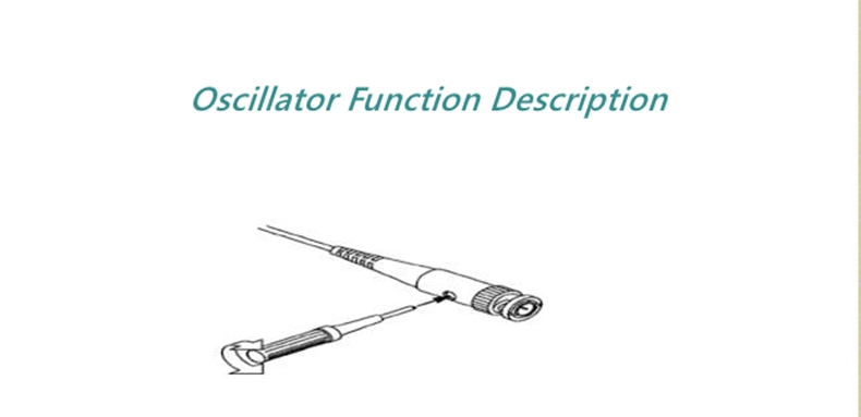
- Probe attenuation setting: the probe attenuation coefficient setting will affect the vertical scale reading value of the signal. Ensure that the attenuation switch multiple on the probe matches the probe attenuation multiple option in the oscilloscope system settings. When the switch is set to X1, the oscilloscope is set to X1, and when the switch is set to X10, the oscilloscope is set to X10.
- Note: when the probe is set to X1, the probe labeled as 6MHz/X1 will limit the bandwidth of the oscilloscope to 6MHz input; to use the full bandwidth of the oscilloscope, make sure to set the switch to X10 or use a higher specification probe.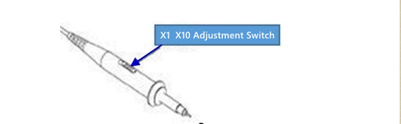
Oscillator Function Description:
- Rolling mode: when the horizontal time base is slower than 100ms/div, the oscilloscope automatically enters rolling mode; Triggering and horizontal position setting in rolling mode are not controlled; Waveform scrolling display from left to right; The rolling mode is suitable for low-speed signals and can observe the waveform change trajectory for a long time according to measurement requirements.
Trigger System:
- Usually, in oscilloscope measurement, it is necessary to obtain a specific or prominent difference (continuous or instantaneous) waveform in the circuit for observation and analysis. The trigger system can be used to set the conditions. When the collected signal meets the set conditions, the system automatically obtains the current waveform and displays it on the screen.
- Trigger cursor setting: when on the main interface, press F3 to select the trigger cursor menu. Press the up and down arrow keys to adjust the position of the trigger cursor. When adjusting, the trigger level value in the right and upper corners of the screen will follow the change (the trigger level value is based on the vertical waveform position as a reference point)
- Trigger method: press the MENU key to expand the screen pop-up menu, and press F2 to select the trigger mode. There are three types in total:
1. Automatic: automatic triggering will collect and refresh waveform records in real-time, without retaining waveforms.
2. Normal: when the amplitude of the collected signal reaches the set triggering level value, the triggering system will lock the waveform and keep it displayed on the screen. The oscilloscope is still continuously collecting, and when triggered again, the waveform on the screen will be updated to the current waveform again, indicating continuous triggering.
3. Single time: when the amplitude of the collected signal reaches the set triggering level value, the triggering system will lock the waveform and keep it displayed on the screen. After the waveform acquisition is completed, the STOP status will be displayed, and the oscilloscope will stop signal acquisition; To trigger again, press HOLD to cancel STOP and enter the waiting state.
- Trigger Edge: press the MENU key to pop up an extended menu on the screen, and then press F3 to select; Set two triggering methods: rising edge and falling edge, as shown in the following figure: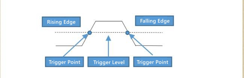
- Rising edge trigger: refers to the signal amplitude that triggers the system to recognize the climbing process. When the amplitude reaches the triggering level, the trigger acts.
- Falling edge trigger: refers to the signal amplitude that triggers the system to recognize the falling process. When the amplitude reaches the triggering level, the trigger acts.
Measurement:
- Automatic measurement: when measuring the waveform of an unknown signal, you can press the AUTO button, and the measurement system will automatically recognize and adjust the waveform amplitude in time, and display the matched waveform on the screen.
- Manual measurement: manually set parameters such as predicted waveform voltage, time base, cursor position, triggering, coupling method, probe attenuation, etc; Connect the measuring circuit to the oscilloscope probe, observe the waveform and read the relevant measurement values.
- Measurement value: Press the MENU key to pop up an expansion menu on the screen, and then press the right arrow button to enter the next menu. At this time, press the F4 key to select whether to turn on or off the measurement value; The measured values FreQ:, VPP:, Vmax: are normally displayed and not controlled by the switch; Vmin:, RMS:, Prd: can be set to display and hide according to requirements.
How to save measurement waveforms?
- When it is necessary to save the measured waveform, press and hold the HOLD/SAVE key for 2 seconds. When a save prompt pops up on the screen, release the button and the oscilloscope will automatically save the current measured waveform data in the form of a picture with a serial number saved in the memory.
How to view and obtain stored waveforms?
- Press the MENU key to pop up an expansion menu on the screen, then press the right arrow key to enter the next page menu, and press the right arrow key again to enter the third page menu. At this time, press the F3 key to save the data and enter the memory menu.
- Connect the oscilloscope to the computer by connecting to the TYPE-C data cable, click on the USB disk, open the pic folder for viewing, or download the waveform to the computer for easier organization and analysis.
- Press F2 to return to the measurement interface.
Auxiliary Functions:
- Language setting: press the MENU key to pop up an extended menu on the screen, then press the right arrow button to enter the next menu page. At this time, press the F1 key, and select two oscilloscope language modes: Simplified Chinese or English according to personal usage habits.
- Automatic shutdown: press the MENU key to pop up an extended menu on the screen, and then press the right arrow button to enter the next menu page. At this time, press the F2 key to select the automatic shutdown time; According to the usage frequency, you can choose from 15 minutes, 30 minutes, 60 minutes, 120 minutes, or unlimited (long open). If used temporarily for a short period of time, it is recommended to choose automatic shutdown within 15 minutes to save power; If used continuously for a long time, you can choose between 120 minutes or unlimited time.
Oscilloscope:
- Backlight brightness: press the MENU key to pop up an extended menu on the screen, and then press the right arrow button to enter the next page. At this time, press the F3 key to select screen backlight brightness adjustment; Set the brightness level to 30%, 50%, 80%, and 100%; It is recommended to adjust the brightness of indoor lighting by 30%, or adjust it to a more comfortable level according to different sensory environments.
- Baseline calibration:
Press the MENU key to pop up an extended menu on the screen, then press the direction right button to enter the next menu, and press the direction right button again to enter the last menu. At this time, press the F1 key to perform baseline calibration.
When there is a significant deviation in environmental temperature or when there is a baseline zero shift phenomenon found after a long period of unused use, baseline calibration can be carried out; Please note the following two points during calibration:
1. Do not connect the probe or input signal during calibration, as it may cause calibration deviation or damage the instrument.
2. Do not perform any other operations during the calibration process until prompted to complete the calibration
- Restore settings: press the MENU key to pop up an extended menu on the screen, then press the direction right button to enter the next menu, and press the direction right button again to enter the last menu. At this time, press the F2 key to enter, and the oscilloscope will restore its factory settings and shut down; If you need to turn on the computer, press and hold the power button to turn it on.
Multimeter Input Terminal:
- 10A: Input port for current measurement (<= 9.999A)
- mA: Input port for current measurement (<= 99.99mA)
- COM: Common (return) port for all measurements
- V ohm Hz: Input port for AC/DC voltage, resistance, capacity, frequency, temperature, on/off, diode measurement
- Negative sign: When a negative value appears, the screen will display a negative sign prompt
- Main display: Display the measured value of the multimeter, with a maximum display of 9999 words
- Unit symbol: displays the unit symbol of the measured data
- Measurement method:
Automatic range (AUTO): The multimeter automatically selects the appropriate testing range
Manual measurement (MANU): Press the RANGE key to choose to switch to the specified test range
- Max: Display the maximum reading value during measurement
- Min: Display the minimum reading value during measurement
- AVG: Display AVG average value during DC voltage, resistance, and capacitance measurements
- Hz: Display the reading value of AC frequency (Hz) during AC voltage and current measurement
- Temp: Display Fahrenheit (F) reading during temperature testing
- Voltage range: Press F1 to select the voltage measurement range, and then press F1 to select AC/DC AC/DC switching
- Resistance, capacitance, diode, on/off range:
Press F2 key to enter the resistance measurement file
Press F2 on the resistance measurement interface to enter the on/off mode
Press F2 on the on-off interface to enter the diode mode
Press F2 on the diode level interface to enter the capacitor level
- Current range: Press F3 to switch to the current measurement range, and the original F4 menu on the current testing interface will display mA range
- Millivolts, temperature measurement range: Press F4 on the non current testing interface to enter the DC millivolt voltage measurement range, then press F4 to enter the AC millivolt range, and then press F4 again to enter the temperature measurement range.
Precaution:
- Disconnect the circuit path to be tested, connect the probes in series to the circuit, and turn on the power. Read the current value displayed on the display screen.
- The measured current should not exceed the rated maximum test value, otherwise it may damage the instrument and endanger personal safety.
- If the current to be tested is unknown, it should be tested and judged at the A end first, and then the test port and gear should be selected based on the displayed value.
- It is strictly prohibited to input voltage in this gear state.
Resistance Measurement:
- Insert the black probe into the COM end and the red probe into the V ohm Hz end.
- Press F2 key to enter the resistance range.
- Use the probe to contact the desired circuit test point.
- Read the resistance value measured on the display screen.
- Before measuring the resistance, it is necessary to confirm that all power sources in the tested circuit have been turned off and all capacitors have been fully discharged.
- It is strictly prohibited to input voltage in this gear state.
Testing On/Off:
- Insert the black probe into the C0M end and the red probe into the V ohm Hz end.
- Press the F2 key when in the resistance range to enter the on/off range.
- Connect the probe to two points of the circuit to be tested, and if the built-in buzzer sounds, it indicates a short circuit.
- Disconnect the circuit path to be tested, connect the probes in series to the circuit, and turn on the power. Read the current value displayed on the display screen.
- The measured current should not exceed the rated maximum test value, otherwise it may damage the instrument and endanger personal safety.
- If the current to be tested is unknown, it should be tested and judged at the A end first, and then the test port and gear should be selected based on the displayed value.
- It is strictly prohibited to input voltage in this gear state.
Diode Measurement:
- Press F2 once to enter the diode mode during the on/off mode.
- Connect the red probe to the positive pole of the diode to be tested, and the black probe to the negative pole of the diode to be tested, and then read the forward bias voltage displayed on the display screen. If the polarity of the test wire is opposite to that of the diode, or if the diode is damaged, the screen displays "OL".
- It is strictly prohibited to input voltage in the on/off and diode gear states.
- Before testing, the power supply of the circuit should be disconnected and all high-voltage capacitors should be discharged.
Capacitance Measurement:
- Insert the black probe into the COM end and the red probe into the V ohm Hz end.
- Press the F2 key once while in the diode position to enter the capacitor mode.
- Connect the red probe to the positive electrode of the capacitor to be tested, and connect the black probe to the negative electrode of the capacitor to be tested.
- After the reading stabilizes, read the capacitance value displayed on the display screen.
- Before testing, the power supply of the circuit should be disconnected and all high-voltage capacitors should be discharged.
Temperature Measurement:
- Insert the black plug of the thermocouple into the COM end and the red plug into the V ohm Hz end.
- Press F4 three times to enter the temperature range; At this point, the screen defaults to displaying room temperature, the main display screen will display degrees Celsius, and the secondary display screen will display degrees Fahrenheit.
- Contact the measuring point with the temperature probe of the thermocouple.
- Read the temperature value displayed on the display screen.
- It is strictly prohibited to input voltage in this gear state.
Precaution:
- Except for replacing batteries and fuses, do not attempt to repair this product or change the circuit unless you have qualified qualifications and corresponding calibration, performance testing, and maintenance instructions.
- Please use a damp cloth and mild cleaning agent to clean the casing, do not use corrosive agents or solvents. If there is dust or moisture on the test port, it may affect the accuracy of the reading.
- Before cleaning the product, please remove all input signals.
Package Included:
- 1 x Set of ZT-702S Handheld Oscilloscope